Slab Base:
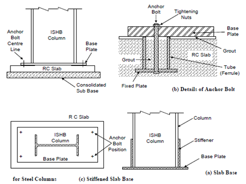
Figure (a) shows a slab base, which consists of a reinforced concrete slab, which is laid at a suitable depth after providing a firm sub-base or screed. The load from the column to the RC slab is transmitted through a flat horizontal steel base plate. The steel column is either riveted or welded to the base plate, through a proper connection. The plate is fixed to the RC slab by means of suitable hold-fast (or anchor) bolts, that is then properly grouted with cement. In order to allow gradual increase in area an RC pedestal is often provided over the RC slab. The anchor bolts are tightened such that they develop a tensile stress, which is approximately 90% of the proof stress. They are enclosed in a ferrule or pipe, which is embedded in the concrete as shown in Figure (b). A tolerance of about 2 mm is provided in the bolt holes for minor alignment of the column. The alignment of columns and their levels are properly checked before final grouting is done.

Figure: Slab Base
The base plates are designed to withstand the axial load, horizontal shear or external moments transmitted through the base of the column, and should be of sufficient area to avoid crushing of concrete. The concrete RC slab in its turn should be of sufficient area to distribute the load to the sub-base such that the upward soil pressure does not exceed the safe bearing capacity of the soil. The RC slab is designed to withstand stress due to this upward soil pressure. For larger loads, sometimes stiffeners are needed for the base plates.