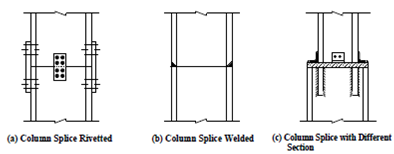
Column Splice:
The length of structural steel members as available in the market or site is limited up to 15 m maximum, or even less. Within multistoreyed buildings, for convenience of fabrication it is kept at about 5 m lengths. Also the cross sectional area of columns may vary from one storey to another. Due to these reasons columns are joined with each other along their lengths. Such joints are called column splices. The design of the splice depends upon the surface quality of the column ends at the joint. If the ends are machined and milled, so as to provide good contact area along the whole cross-section, the splice plates are free from any force transmitted. However, they have to be designed against tensile forces caused by lateral (wind/earthquake) loading and also due to erection stresses. If the ends of the columns are not milled, the force from the upper column is transmitted to the lower one through the splices. This is to be designed to transmit all the forces to which they are subjected as a single cover butt joint welded or riveted as the case may be. Various types of column splices are shown in Figure.
IS : 800 stipulates that column splices and butt joints of struts and compression members depending on contact for stress transmission shall be accurately machined and close butted over the whole section with a clearance not exceeding 0.2 mm locally at any place. The ends of shafts together with the attached gussets, angles, channels, etc. after riveting together should be accurately machined so that the parts connected butt over the entire surfaces of contact. (Reduction in thickness by machining should not be more than 2 mm.)

Figure: Column Splices