Plain Milling:
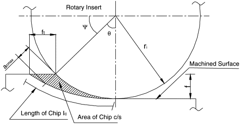
Figure 4 illustrated a chip (shaded part) produced throughout plane milling by one tooth (also shaded) of the rotating cutter. The linear feed is being provided to the workpiece. Feed per tooth is defined as ft, d as depth of cut, D is cutter diameter and V is peripheral speed of the cutter. O is the original location of the center of the cutter and O' is the new center location after imparting a feed equal to ft.
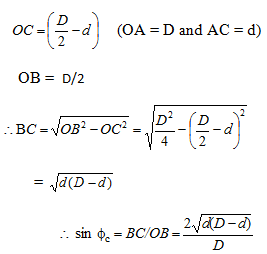
The equation to find out Amax is mainly derived by using the geometry of the chip as follows :
From Figure 4

The tooth contact angle (Ð OCB) fc is given following
fc =cos-1((D-2d)/D)

Figure 4 : Chip Cross-section during Slab Milling by Single Tooth
(b) The chip thickness (t) at an instant ( at section x) of the tooth might be evaluated as
t = ft sinf ----------- (26(b))
(f is shown in Figure 4. Note that at f = p/2, t = ft).
Assume Z is number of teeth in a cutter and N is the rotational speed of cutter (RPM). After that the feed rate (f) per minute is provided by
f = ft N Z --------------- (26(c))
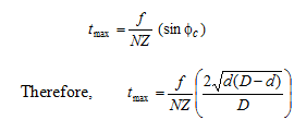
Hence,  (From Equation 26(b) and 26(c)) ---------- (26(d))
Maximum chip thickness (tmax) will take place when. Therefore,

(c) In plain milling along straight teeth cutters (helix angle = 0o), the width of the cut (W) is equivalent to the width of the workpiece (supposing the cutter width greater than the workpiece width). Therefore, the maximum cross-sectional area of the chip Am is provided by
Amax = W tmax .------------(28)
As might be seen from Figure 4, the chip thickness differs from zero to the maximum. Therefore, mean cross-sectional area ( ) might be taken as approximately half of Amax.
A'= 0.5 Amax ------------ (29)
In case of helical cutters (helix angle > 0), various teeth of the cutter are engaged along the workpiece simultaneously. In this case, the mean cross-sectional area of the chip might be evaluated by volumetric material removal rate (MRRv, m3/min) and cutter speed (m/min).
 ------------(30)