Uniform Velocity:
Velocity, V = const. . . . (6.1)
Or,
dy /dt = const. (C )
∴ y = C t + A
Here A is constant of integration.
As
y = 0 at t = 0 ∴ A = 0
∴ y = C t . . . (6.2)
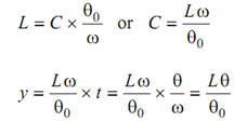
Assume 'L' is the upmost lift of the follower and θ0 & θr be angles for the rise & return of the follower.
While θ= θ0 , y = L
Thus, from Eq. (6.2)
 . . . (6.3)
Likewise, for return stroke,

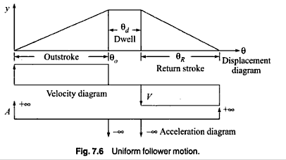
Above Eq. (6.3) implies that follower displacement is proportional to cam rotation. As slope is constant, displacement-angle graph shall be a straight line. The diagram for, velocity, displacement, acceleration and jerk are illustrated in given figure. It can see in the figure that jerk and acceleration are infinite at the starting and ending of the motion. These results in infinite inertia forces that mean that the follower shall loose contact shall cam or press it too difficult. Thus, this kind of motion is not appropriate from practical viewpoint. However this type of motion may be modified to set practical consideration. This may be done by permitting consistent rate of increase in velocity at the starting and consistent rate of decrease in velocity at the ending of the motion for compact periods. This shall result in rounding off the sharp cornors in displacement diagram. The modified diagram is illustrated in Figure.
