Dynamically Equivalent System:
The slider-crank mechanism is one of the most commonly utilized mechanisms. It is utilized into prime movers, punching press, reciprocating compressors etc. The reciprocating mass involves mass of the piston and partition of the mass of the connecting rod. One ending of the connecting rod reciprocates having cranked. We need to replace this link by a mass less link that is dynamically equivalent having two point masses m1, at the piston ending and m2 at the crank ending.
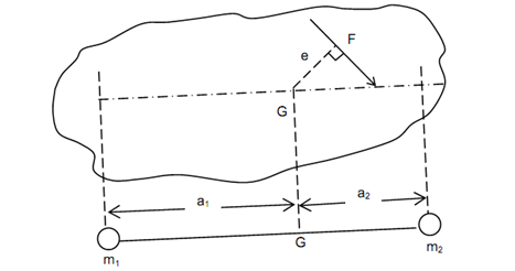
In a general case, we may think of a rigid link of any shape as illustrated in Figure. Let this be subjected to a system of forces whose resultant is say 'F' producing a couple Fe regarding centre of gravity G. This force generates linear acceleration 'a' ( = F /m) and
angular acceleration 'α' ( = F e /I) , where I is mass moment of inertia around a perpendicular axis through G.

For the massless link with point masses m1 and m2 to be dynamically equivalent, this must generate similar accelerations 'a' and 'α' because of the action of similar force 'F'.
Assume a1 and a2 be the distances of the point masses m1 and m2 respectively from centre of gravity G.
For a dynamically equivalent system with accelerations 'a' and 'α'
(a) Total mass must be similar, that means
m1 + m2 = m . . . (11.1)
(b) Position of centre of gravity must remain similar, that means
m1 a1 = m2 a2 . . . (11.2)
(c) Mass moment of inertia should be similar, that is
 . . . (11.3)
These three equations (11.1) to (11.3) must be satisfied for total dynamical equivalence. There are four unknowns (m1, m2, a1 and a2) and the three equations. Thus, one of these four variables may be arbitrarily supposed and other three can be estimated to provide a unique solution.
For slider-crank mechanism, it shall be convenient to contain mass m1 along the piston and mass m2 at the crank ending and therefore a1 and a2 are decided beforehand. But in that case all of the three equations cannot be satisfied.
From equation (11.1) to (11.3),
and mass moment of inertia = m a1 a2.
If masses m1 and m2 are situated at above mentioned positions the equation (11.3) will not be satisfied. The change in moment of inertia shall be
= I - m a1 a2
= m k 2 - m a1 a2 = m (k 2- a1 a2)
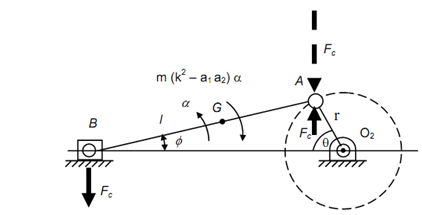
The correction couple needs to be determined and it will be m (k 2 - a1 a2) α. This couple may be thought of applied by the two forces FC as illustrated in given figure.

Hence ,
FC l cos φ= m (k 2 - a1 a2 ) α
or,
 . . . (11.4)
The correction in the turning moment shall be equivalent to the moment of force FC illustrated by the dashed line regarding the crank centre.
Correction couple =- FC r cos θ


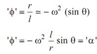
Applying Different ion twice w.r.t. 't' and letting 'ω' constant

Correction couple
 . . . (11.5)