Head flow meters:
Head flow meters operate on the principle of placing a restriction within the line to cause a differential pressure head. A differential pressure that is caused through the head is measured and converted to a flow measurement. An Industrial application of head flow meters incorporates a pneumatic or electrical transmitting system for remote readout of flow rate. Commonly, the indicating instrument extracts the square root of the differential pressure and shows the flow rate on a linear indicator.
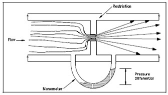
There are two components in a head flow meter; the main part is the restriction in the line, and the secondary part is the differential pressure measuring device. Below figure displays the basic operating features of a head flow meter.

Figure: Head Flow Meter
The flowpath restriction, like as an orifice it causes a differential pressure across the orifice. That pressure differential is measured through a mercury manometer or a differential pressure detector. By this measurement the flow rate is determined from the known physical laws.
The head flow meter in fact measures volume flow rate rather than mass flow rate. A Mass flow rate is simply calculated or computed from volumetric flow rate through knowing or sensing temperature and/or pressure. The Temperature and pressure affect the density of the fluid and, thus, the mass of fluid flowing past a certain point. A true mass flow rate signal can be obtained if the volumetric flow rate signal is compensated for changes in temperature and/or pressure. Within Thermodynamics it is defined in which temperature and density are inversely proportional, when pressure and density are directly proportional. To display the relationship among temperature or pressure, a mass flow rate equation is frequently written as either Equation 1 or 2.
m = KA √?P(P) (1)
m = KA √?P(1/T) (2)
where
m = mass flow rate (lbm/sec)
A = area (ft2)
?P = differential pressure (lbf/ft2)
P = pressure (lbf/ft2)
T = temperature (°F)
K = flow coefficient
The flow coefficient is constant for the system based mainly on the construction features of the pipe and category of fluid flowing by the pipe. A flow coefficient in every equation holds the appropriate units to balance the equation and gives the proper units for the resulting mass flow rate. An area of the pipe and differential pressure are used to calculate volumetric flow rate. As begin above, that volumetric flow rate is converted to mass flow rate through compensating for system temperature or pressure.