Circuitry:
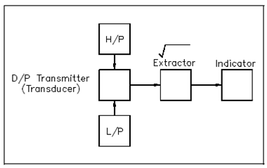
Figure displays a block diagram of a classical differential pressure flow detection circuit. A DP transmitter operation is dependent on the pressure variations across a venturi, orifice, or flow tube. That differential pressure is used to position a mechanical device like as a bellows. A bellows acts against spring pressure to reposition the core of a differential transformer. The transformer's outcome voltage on every of two secondary windings varies along with a modification within flow.

Figure: Differential Pressure Flow Detection Block Diagram
A loss of differential pressure integrity of the secondary parts, the DP transmitter, will introduce an error into the denoted flow. This loss of integrity implies an impaired or degraded pressure boundary among the high-pressure and low-pressure sides of the transmitter. The loss of differential pressure boundary is caused through anything which results in the high- and low-pressure sides of the DP transmitter being permitted to equalize pressure.
As earlier discussed, flow rate is proportional to the square root of the differential pressure. An extractor is used to electronically calculate the square root of the differential pressure and gives an outcome proportional to system flow. The constants are determined through selection of the suitable electronic components.
The extractor output is amplified and sent to an indicator. The indicator gives either a local or a remote indication of system flow.