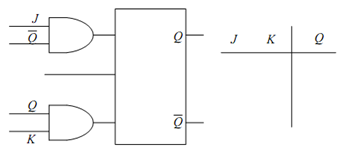
JK-type Flip Flops:
JK Flip Flop may be achieved from the clocked SR Flip Flop of Figure (b) by adding two additional AND gates at the input as illustrated in Figure (a). For this case, S = J Q¯ and R = KQ. The truth table for JK Flip Flop is drawn in Figure (b). Let us attempt to arrive at this truth table of JK Flip Flop from the detailed truth table of Table. There are four possible combinations of inputs J and K. For each of these combinations there are two possible states of Q, therefore, there are 8 rows in the Table. From the values of J, K, Q and Q¯ , the values S and R are calculated and tabulated in different columns in the same Table. By using these values of S and R we may calculate the values of Q at the next time instant. Note down that columns 1, 2 and 8 of this Table form the JK Flip Flop truth table of Figure (b). In Table, basically toggle means the output shall become complement of the last state.
Table: Truth Table of JK Flip Flop
|
J
|
K
|
Q
|
Q
|
S
|
R
|
Q
|
|
0
|
0
|
0
|
1
|
0
|
0
|
Last State
|
Last State
|
|
0
|
0
|
1
|
0
|
0
|
0
|
Last State
|
|
1
|
0
|
0
|
1
|
1
|
0
|
1
|
1
|
|
1
|
0
|
1
|
0
|
0
|
0
|
Last State
|
|
0
|
1
|
0
|
1
|
0
|
0
|
Last State
|
0
|
|
0
|
1
|
1
|
0
|
0
|
1
|
0
|
|
1
|
1
|
0
|
1
|
1
|
0
|
1
|
Toggle
|
|
1
|
1
|
1
|
0
|
0
|
1
|
0
|

Figure: (a) Additional Connections and Logic Gates of an S-R Flip-Flop to Modify to a JK Flip-Flop, and (b) Truth Table