Balancing of Large Rotors:
The method explained in Section 19.4.1 for thin disc may be extended for the big rotors which are balanced in situ. In this case, there are two balance planes & two measurement planes.
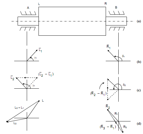
We select two measurement planes say A & B and two convenient balancing planes say L & R. Consider L1 and R1 be the initial readings of vibration levels measured respectively with phase angles γ1 and δ1.
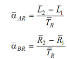
The phase angles are measured along same reference through the test. Figure 10(b) illustrated the values L1 and R1. In the second run a trial mass TR is located at a convenient position in plane R and assume the observation respectively be L2 and R2 at angles γ2 and δ2 in the left and right planes of measurement A & B as illustrated in Figure 10(c). The difference among the readings of first run and second run shall be the effect of trial mass. Consider and be the effect coefficients on the right and left planes for trial

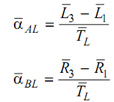
The trial mass is eliminated from plane R and place another trial mass. in the left plane and the test is repeated. Assume L3 and R3 by the observation respectively at angles γ3 and δ3. Consider the influence coefficient for this case be


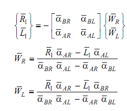
After calculating these four influence coefficients, correct balance masses may be find out. Assume the correct balance masses are respectively and
and for right and left planes. As the initial reading R1 and L1 defined the unbalance in the machine, for correcting (- R1 ) and (- L1 ) balancing is needed

These masses may be calculated and mounted on the balancing planes for balancing.
