Balancing of a Thin Disc:
The class of rotors as industrial fan, wheel, blowers etc. may be considered as thin disc. A pick-up is utilized to measure oscillations of the thin disc in say vertical direction and the output is displayed on the double oscilloscope. A sine wave generator is associated to the disc and produced sine wave is fed to the second beam of the similar oscilloscope. The sine wave is utilized as a reference for measuring phase of the pick-up signal
Primary the disc is rotated at a speed that is adequate to produce measurable amplitude of oscillation. Consider A1 be the amplitude and θ1 be the phase difference along reference to the sine wave. Next a trial mass 'mi' is associated to the disc at a known angular location and at a known radius. The disc is rotated at the similar speed. Consider the amplitude of this oscillation be A2 and assume phase difference be θ2. Now both of these vectors are plotted. Consider
A1 be defined by and A2 by as illustrated in Figure 8(c). The vector defines the effect of the trial mass 'mi'. Therefore, to nullify the effect of a balancing mass mb must be added at the similar radius as that of trial mass such that
mb = m i (oa/ ab)
at an angle φ clockwise in this case.
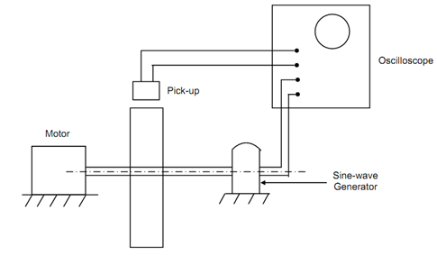
(i)
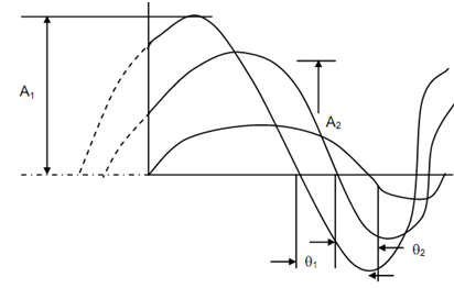
(ii)
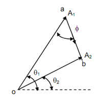
(iii)
If a phase meter is employed the utilization of sine wave generator may be avoided. In the field balancing measurement of phase might be hard. In that case, the following four readings might be taken for vibration amplitude
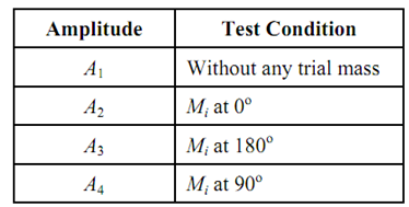
When taking these runs along trial mass (less three runs) the radial distance of the trial mass must be kept similar.
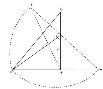
Draw a triangle 'abc' by taking ab = 2A, ac = A2 and bc = A3 as illustrated in Figure 9. Consider 'd' be the middle pt of ab. The magnitude of the balancing mass is specified by
mb = m (ad / dc) and angle φ =∠ adc
If magnitude of A4 is given by ac, the angle must be calculated counter clockwise. If magnitude of A4 is given by af, angle φ must be measure in clockwise sense.
