The pentode
The electrons in the tetrode can strike plate with extreme speed, especially if plate voltage is high. The electrons may bombard the plate with such force that some of them bounce back from the plate. Imagine hurling a baseball into a

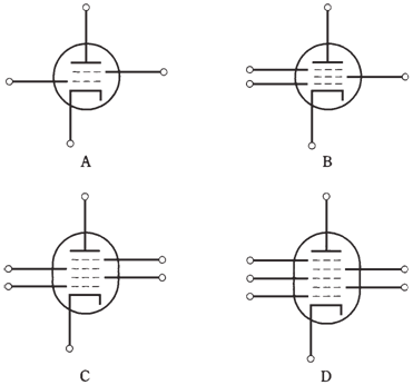
Figure--At point A, a tetrode tube. At point B, a pentode; at C, a hexode; at point D, a heptode.
bushel basket full of the other baseballs. If you throw the ball hard, some of the other balls may be jostled out of the basket. Many of these electrons result in leaking out through the screen grid, instead of going through the plate circuit of tube. The result is diminished plate current and increased the screen current. As it’s the plate current which produces the output signal for tube, this secondary emission hinders the performance of tube. If the secondary emission is wide, it can cause screen current so high that screen grid may get damaged.
The problem of secondary emission can be solved with by placing yet another grid, called as suppressor grid or suppressor, between screen and plate. The suppressor reduces the capacitance between control grid and plate still more than is the case with tetrode.Greater gain and stability are possible with the pentode, or tube with 5 elements, than with a tetrode or triode. The schematic symbol for a pentode is shown at point B in the figure given below. The suppressor grid is grounded generally, or connected directly to the cathode. It, thus, carries a negative charge with respect to screen grid and plate.