Free Body Diagrams:
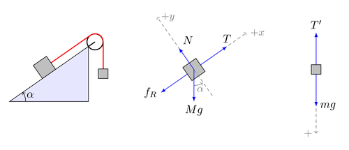
To study any structure, you should be in a position to identify all the forces acting on it. A structure can be divided into parts for simplicity. If you separate a body from its surroundings and draw a diagram to represent that body and indicate all the forces from the surroundings that act on it; such a diagram is called a free-body diagram.
Example
Consider the propped cantilever shown in Figure. To draw the free-body diagram for the beam, isolate the beam through the surroundings. The fixed and the roller hinge supports will be replaced by constraining forces offered by them. All external loads shall also be replaced by forces exerted on it and then the resulting diagrams are called as free-body diagram of the beam.
Solution
Free-Body Diagram for the beam in Figure shows :
1. beam AB,
2. constraining forces HA, VA and MA offered by the fixed support at A (directions and sense can be confirmed easily later on, as shall be made clear by numerical examples),
3. constraining forces RB offered by the roller support B,
4. The external load (F) working at C.

Figure