Charpy Impact Test
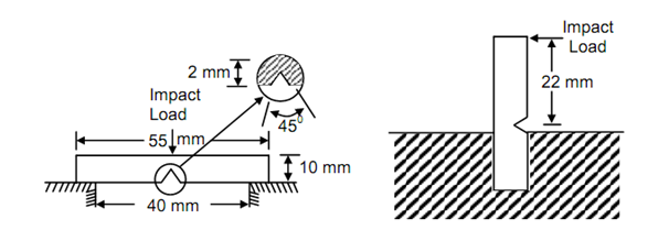
The Charpy impact test is performed on a square cross-section specimen, having a notch on one side in the central cross-section. The specimen is placed in charpy impact testing machine shown in Figure 24 such that swinging pendulum strikes the specimen at the central cross-section but on the opposite side of the notch. The specimen is simply supported on the platform of the machine as illustrated in Figure 25(a). The commonly used impact specimen is 10 mm square cross- section beam of 55 mm length, supported over 40 mm span and having a V-notch in the central plane whose included angle is 45o, depth is 2 mm and root radius is 0.25 mm.

Figure: Impact Test Specimens
The charpy test machine shown in Figure 24 is rigid and strong structure of two columns on a heavy base. The columns carry a heavy swinging pendulum at their top which swings on a frictionless pin, and support platform at the bottom for the specimen. When the pendulum is in its vertical position its striking edge is level with the central cross-section of the specimen. The mass of the striker (or hammer) is concentrated in vertical plane. A circular disc scale mounted centric with the pin of the pendulum reads its position but is often calibrated in terms of the potential energy of the pendulum.
To perform the experiment the specimen is first placed in position by the help of a centring device, the pendulum is raised to and held at its extreme position and then allowed to fall. At its extreme position, h1 from the specimen, the pendulum has potential energy Wh1 where W is the weight of the pendulum. In this position the arm of the disc scale is in its extreme position, reading total amount of energy stored in the hammer. The speed of approximately released from its raised position and strikes the specimen at a speed of approximately 4.8 m/sec. Under this condition the specimen is forced to bend with a rate of 103 mm/mm (sec) resulting into instantaneous fracture or plastic deformation. The pendulum continues its swing after fracturing or deforming the specimen and rises to height of h2. Thereafter, the pendulum swings back to oscillate pointer which does not swing back with the pendulum. As already pointed out the disc scale is calibrated to read energy and the position of the dead pointer reads the difference of potential energies of the pendulum in two extreme positions corresponding to h1 and h2. Naturally this difference of the energy is that which was absorbed in fracturing the specimen. Thus if Uf denotes the impact roughness,
Uf = W (h1 – h2) ----------- (17)
It may, however, be recognised that some energy loss may occur in the bearing of the pendulum and also due to resistance of air offered to swinging pendulum. These two losses may be determined by simple experiment in which the pendulum is allowed to fall from is extreme position without placing the specimen in its path. The other extreme position to which pendulum rises will be slightly lower than its initial position. The difference of the potential energies in two positions, indicated by the position of the dead pointer, is the loss of energy to bearing friction and air resistance. This energy loss (UL) has to be subtracted from Uf to obtain corrected value of impact toughness, i.e.
Uf = Wh1 – Wh2 – UL ------------ (18)