Thevenin’s theorems
Theorem: Thevenin’s theorem defines that any two output terminals of an active linear network having independent sources (i.e., it involves voltage and current sources) can be substituted by a simple voltage source of magnitude VTH in series with a single resistor RTH, where RTH is the equivalent resistance of the network whenever looking from the output terminals A and B with all sources (i.e., current and voltage) eliminated and substituted by their internal resistances and the magnitude of VTH is equivalent to the open circuit voltage across the A and B terminals.
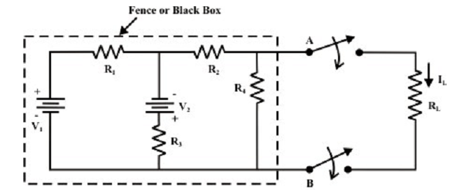
A simple circuit is as shown in figure below is considered to exemplify the concept of equivalent circuit and it is all the time possible to view even a very complex circuit in terms of much simpler equivalent source and load circuits. Consequently the decrease of computational complexity which includes in resolving the current via a branch for dissimilar values of load resistance (LR). In most of the applications, a network might contain a variable component or element whereas other elements in the circuit are reserved constant. When the answer for current (I) or voltage (V) or power (P) in any component of the network is preferred, in such situations the entire circuit require to be analyzed each time with the change in component value. In order to shun such repeated computation, it is preferable to introduce a technique that will not have to be replicated for each value of variable component.
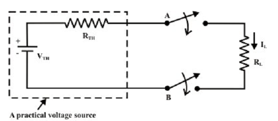
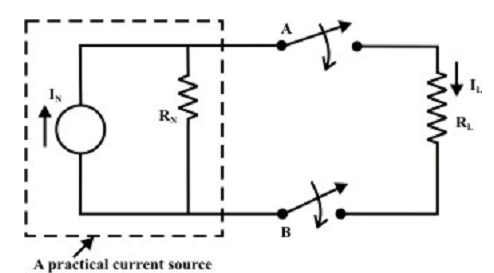
These tedious computation burdens can be avoided provided the fixed portion of such networks could be transformed into a very simple equivalent circuit which symbolizes either in the form of practical voltage source termed as Thevenin’s voltage source (VTH = magnitude of voltage source; RTH = internal resistance of the source) or in the form of practical current source termed as the Norton’s current source (IN = magnitude of current source, RN = internal resistance of current source). In true logic, such translation will significantly simplify the study whereas the load resistance changes. However the conversion method accomplishes the similar goal, it has certain benefits over the methods which we know.
Let us consider the circuit as shown in figure below. Our difficulty is to find a current via RL by using various methods; then the following observations are prepared.

Find:
• The Mesh current technique requires 3 equations to be resolved.
• The Node voltage technique needs 2 equations to be resolved.
• The Superposition technique needs a complete solution via load resistance (RL) by considering each separate source at a time and substituting other sources by their internal source resistances.
Assume, when the value of RL is changed then the three mesh current technique or two equations (i.e., node voltage technique) require to be resolved again to find the new current in RL. Likewise, in situation of superposition theorem each time the load resistance RL is changed, the whole circuit has to be examined all again. Most of the tedious mathematical work can be avoided when the fixed portion of the circuit (as shown in figure above) or in another words, the circuit contained within the imaginary fence or black box with two terminals A and B, is substituted by the simple equivalent voltage source (as shown in figure below) or current source (as shown in next figure below).

Figure: Circuit is equivalently substituted by a simple practical voltage source

Figure: Circuit is equivalently substituted by a simple practical current source