Adding impedance vectors:
There is resistance, as well as reactance, in an alternating current series circuit containing a coil and capacitor. This takes place when the coil wire has significant resistance (it's never a perfect conductor). It might be the case because a resistor is deliberately connected into the circuit.
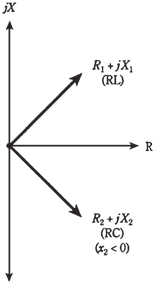
Whenever the resistance in a series circuit is significant, the impedance vectors no longer point straight up and straight down. Instead, they run off towards north east (for the inductive part of circuit) and southeast (for capacitive part). This is shown in the figure given below. When vectors do not lie along the single line, you are required to use vector addition to be sure that you get correct resultant. Fortunately, this is not difficulat.
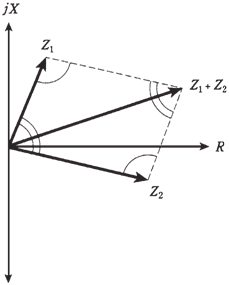
In the figure given below the geometry of vector addition is shown. Construct a parallelogram, by using the 2 vectors Z1=R1=jX1 and Z2 =R2 = jX2 as 2 of the sides. The diagonal is resultant. In the parallelogram, opposite to the angles have equal measure. These equalities can be indicated by single and double arcs in figure.

Figure When resistance is present along with reactance, impedance vectors point northeast or southeast.

Figure-- Parallelogram method of vector addition.
Formula for complex impedances in series
Given 2 impedances, Z1=R1 + jX1 and Z2 + R2 + jX2, net impedance Z of these in series is their vector sum, this is given by
Z = (R1+R2) + j(X1 +X2)
The reactances X1 and X2 might be inductive; they might both be capacitive; or one might be inductive and another capacitive. Calculating the vector sum by using the formula is simpler than doing it geometrically with the parallelogram. The arithmetic method is more nearly exact. The resistance and reactance components can be added separately. That is all there is to it.