Adding admittance vectors:
In real life, there is some amount of conductance, as well as susceptance, in an alternating current parallel circuit containing a coil and capacitor. This occurs when the capacitor allows a little bit of current leak through. Often, it is the case because a load is connected in parallel with coil and capacitor. This load can be an antenna, or the input to the amplifier circuit, or some test instrument, or the transducer.
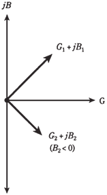
Whenever conductance in a parallel circuit is considerable, the admittance vectors no longer point straight up and down. Instead of that they run off towards the northeast (for the capacitive part of circuit) and southeast (for inductive part). This is shown in the Figure given below.
In problems above, you added numbers, but actually you were adding vectors which just happened to fall along the single line, the imaginary (j) axis of GB plane. In practical circuits, vectors often do not lie along the single line. You have already seen how to deal with these in RX plane. In GB plane, the principle is same.
Formula for complex admittances in parallel
Given 2 admittances, Y1 =G1 + jB1 and Y2 = G2 + jB2, net admittance Y of these in parallel is their vector sum, can be given by
Y =(G1 + G2) + j(B1+ B2)

Figure-- When conductance is present along with the susceptance, admittance vectors point northeast or southeast.
The susceptances B1 and B2 might be inductive; they might be capacitive; or one might be inductive and other capacitive.