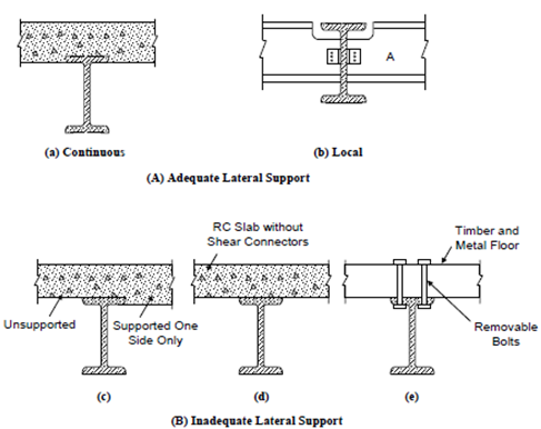
Lateral Support Requirements in Beam Flange:
While the ends of the beams are not restrained against torsion, or when the load applied to compression flange is free to move laterally along with the flange, the above values of l are to be increased by 20%.
For beams, which are provided with members giving effective lateral restraint to the compression flange at intervals along the span, its effective length shall be taken as the maximum distance (centre to centre) between the restraining members. These shall be capable of resisting a force of 2.5% of the maximum force in the compression flange.
For cantilever beams of projecting length L, the effective length l for use in Eq. and the tables shall be as follows : For cantilever built-in at support, but
(i) Free at end, l = 0.85 L
(ii) Restrained against torsion at end, l = 0.75 L
(iii) Restrained against both torsion and lateral deflection at end, l = 0.5 L
For cantilevers having free end but continuous at the support
(i) Unrestrained against torsion, at support, l = 3 L
(ii) Partial restraint against torsion at support, l = 2 L
(iii) Retrained against torsion at support, l = L
Where beams support slab construction, the beam shall be deemed to be effectively restrained laterally if the frictional or positive connection of the slab to the beam is capable of resisting 2.5% of the maximum force in the compression flange of the beam (considered uniformly distributed along the flange). Furthermore, the slab construction shall be capable of resisting this lateral force in flexure and shear (Figure).

Figure: Lateral Support Requirements in Beam Flange