Different possibilities of equilibrium of the link:
The different possibilities of equilibrium of the link are illustrated in Figures 4(i), (ii), (iii), (iv), (v) and (vi). The line of action of force is called as friction axis. The process of determination of friction axis as:

(i) (ii)

(iii) (iv)

(v) (vi)
Figure(4)
Consider the motion of different links in Figure 3(b). The link 2 rotates counter clockwise. For impending slide of link 4, that is piston angle β decreases. The angular velocity of link 3 relative to link 2 is clockwise. For this motion reactive force F23 gives a counter clockwise moment around centre A to oppose the angular impending motion therefore the direction of F23 is as illustrated in Figure 4(e).
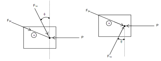
The link 3 contains clockwise angular velocity relative to link 4. Hence, the line of action of force F43 shall be as illustrated in Figure 4(f). The friction axis shall be as shown in Figure 4(d). Figures 5(a) & (b) illustrate the forces respectively in equilibrium for the link 4 for and top and bottom contacts.

Figure (5)