PM Step Motors
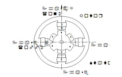
The permanent magnet step motor moves in steps when its windings are sequentially energized. Figure 2 illustrates a permanent magnet rotor surrounded by a two-phase stator. Two rotor sections (N and S) are offset by one half tooth pitch to each other. Since energy is switched from phase 2 to 1, a set of rotor magnets will align with phase 1, and the rotor shall turn one step. If both phases are energized simultaneously, the rotor shall set up its equilibrium midway between steps. Thus, the motor is said to be half-stepping.

Figure 2: Step Motor with Permanent Magnet Rotor
Stepper motors contain a number of benefits that call for their use in motion control applications.
1. Low cost
2. Ruggedness
3. Simplicity in construction
4. High reliability
5. No maintenance
There is virtually no conceivable failure within the stepper drive module that could cause the motor to run away. Stepper motors are easy to drive & control in an open-loop configuration. They just need four leads. They provide excellent torque at low speeds, up to 5 times the constant torque of any brush motor of the same frame size or double the torque of the equivalent brush less motor. This often eliminates the requirements for a gearbox. A stepper-driven system is inherently stiff, with known restriction to the dynamic position error.
In the machine tool, the rotary motion from the drive motor needs to be converted to the linear motion. For this reason a lead screw & nut arrangement is usually used. The Acme thread used in conventional machine tools has more friction and consequently the maximum feed rates are limited. In order to enhance the feed rates to higher values, it is essential to reduce the friction between the nut and the lead screw. Another difficulty with the Acme thread is the clearance between the nut and the screw that causes a considerable backlash. The backlash will drop the accuracy of the dimensions produced. Hence most of the CNC machine tools use a lead screw with a recirculating ball nut.
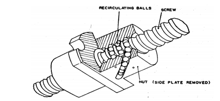
To decrease the friction, the recirculating ball screws utilize rolling friction by the use of balls extremely similar to a ball bearing. The nut is replaced through a series of balls that circulate in a channel built in the form of threads as illustrated in Figure 3. This rolling motion of the balls results in an extremely low coefficient of friction among the screw shaft and nut. The balls at the ending of the thread portion in the nut shall be repositioned back into the starting of the thread form by a deflector or an external return tube.

Figure 3 : A Recirculating Ball Screw and Nut Arrangement (Courtesy : Computer Aided Manufacturing by P. N. Rao, Tewari and Kundra)
To reduce the backlash, the ball screws can be preloaded to eliminate the axial displacement. One of the techniques followed for pre-loading is keeping a spacer between the two parts of the nuts such that they press against the opposite flanks of the thread. This enhanced the axial rigidity of the nut while reducing the axial displacement.
The recirculating ball screws contain a number of advantages compared to the conventional type of screws.
1. The accuracy of the screw can be maintained over a much longer period since the wear of the screw is relatively small.
2. Since the friction is small, it is possible to carry heavier loads at faster speeds.
3. Also, the power required for driving is small due to negligible friction between the nut and the screw.