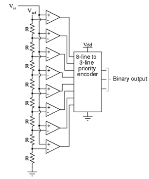
Analog to Digital Converter:
Also called as the parallel A/D converter, the circuit of Figure is the simple to understand. It is composed of a series of comparators, each of comparing the input signal to a unique reference voltage. The comparator outputs associate to the inputs of a priority encoder circuit, which then generates a binary output. Following illustration of Figure illustrates a 3-bit flash ADC circuit. Not only is the flash converter, the easiest in terms of operational theory, but it is the most competent of the ADC technologies in terms of speed, being restricted only in comparator and gate propagation delays. Unluckily, it is the most component-intensive for any given number of output bits. This three-bit flash ADC attains eight comparators. A four-bit version would attain 16 comparators. With each of the additional output bit, the number of needed comparators doubles. Assuming that eight bits is generally considered the minimum essential for any practical ADC (256 comparators needed), the flash methodology rapidly shows its weakness. An added advantage of the flash converter, frequently overlooked, is the ability for it to generate a non-linear output. along with equal-value resistors in the reference voltage divider network, each of the successive binary count represents the same amount of analog signal raise, providing a proportional response. For special applications, though, the resistor values in the divider network may be made non-equal. It gives the ADC a custom, nonlinear response to the analog input signal. No other ADC design can grant this signal-conditioning behaviour with just a few component value changes.

Figure: Parallel ADC