Instrumentation:
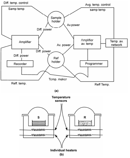
The block diagram of a DSC instrument as display in Figure, basically works on the temperature control of two same specimen holder assemblies. A left half of the block diagram represents the circuit for differential temperature control when right hand side denotes in which for average temperature control. In the average temperature control circuit, a temperature of the sample and reference are measured and averaged and the heat output of the average heater is automatically adjusted so in which the average temperature of the sample and reference rise at a linear rate. The differential temperature use control circuit monitors the difference within temperature among the sample and reference and automatically adjusts the power to either the reference or sample chambers to keep the temperatures equivalent. For getting a thermogram, the temperature of the sample is put on the x-axis and the difference in power supplied (in terms of J s-1 or cal. s-1) to the two differential heaters is shown on the y-axis.
Figure b described the heating arrangement in sample and reference compartments. Here the sample and reference compounds are given along with their own separate heaters, as well as their own temperature sensors so in which both S and R are maintained at identical temperature through controlling electrically the rate at that heat is transferred to them.
Within DSC, samples for analysis range in size from 1 to 100 mg are placed in a sealed sample container. A wide range of heating rate (0.5 to 80°C/min) can be used, DSC instruments are commonly sensitive energy detect heat evolution or absorption at a rate less than one millicalories per second. Electrical signals are amplified and recorded same to DTA and TGA.

Figure: (a) Block diagram of a DSC instrument (b) Heating arrangement in DSC compare this with Figure