Linear amplifier:
In the following, we carry out a DC analysis of the circuit, to ascertain the range of operation over which it acts as a linear amplifier.
Supposing Q1 ≅ Q2 and β1,2 >> 1 so that we can assume IE1, 2 ≅ IC 1, 2, the application of KVL to the base loop gives
VB1 = VBE1 - VBE 2 + VB 2
Under normal operating condition, according to the Ebers-Moll equations, we have
Ic ≅ I s e (VBE /VT)
where Is stands for the reverse saturation current and VT = kT/q. Therefore,
V BE = V T ln ( IC /IS)
From Eqs. (34) and (36), we have
VB1 - VB2 = VT ln [ ( IC1 /IS2) / ( IC1 /IS1)
For matched transistors IS1 = IS2 so that, we get

on the other hand, one can write
IC1 / IC 2= e (VD /VT)
Since,
IC1 + IC 2 ≅ I E1 + I E 2 = I EE = I0
Solving Eqs. (39) and (40) for IC1 and IC2 we obtain
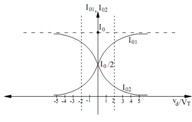
I01 = IC1 = I0 /(1+ e (- VD / VT ) )
and
I02 = IC 2 = I0 /1 + e+ (VD/ VT )
Figure illustrates a plot of these two equations. From the plot we can note that when VD
= 0, i.e. VB1 = VB2, IC1 = IC2 = IEE /2 which is an expected result due to the supposition of matched devices. Also, for VD /VT > 4, IC1 → IEE and IC2 → 0; likewise, for VD /VT → 4, IC1 → 0 and IC2 → IEE. Under either of these two conditions, one of the transistors is saturated and the other is cutoff.

Figure