Types Of Cracks And Modes Of Deformation
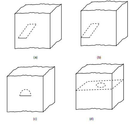
A crack in a material is regarded as discontinuity with a zero radius of curvature at its tip. The cracks may be of different shapes, but two shapes, viz., linear and penny shaped are most commonly handled by mathematics. A line crack is open to the surface of the material while penny-shaped crack is inside the material. Linear cracks are most common and it was explained in section on Fatigue that most cracks initiate on surface, thus these linear cracks open on surface. Figure (a) illustrates cracks of two types. We will consider cracks that open on surface.
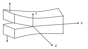
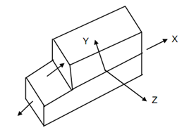
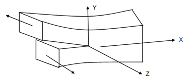
There are, in general, three different ways in which a crack may be deformed or crack faces displaced. Figure (b) illustrates these three modes. The same figure also serves to show coordinates generally chosen to describe a crack. The crack faces lie in x-z-plane while its tip is along z-axis. A crack is normally analysed in two dimensions when it is assumed as a ling along x-axis with origin at its tip.

Figure (a): (a) Linear Crack through Thickness; (b) Edge Crack; (c) Surface Crack; and (d) Penny Shaped Crack

(a) Model I

(b) Model II

(c) Model III
Figure (b) : Modes of Crack Face Displacement
The three modes of crack face displacement are as follows :
Mode I
It is also known as opening or tensile mode. In this case, the crack faces move directly apart with stress acting in y-direction.
Mode II
It is also known as sliding or in plane shearing mode. The crack faces slide over each other in their own plane with displacement perpendicular to leading edge of the crack, i.e. z-axis.
Mode III
It is also known as tearing or antiplane shearing mode. In this case, the crack faces slide over each other but out of their plane. This mode is shown in Figure b (c).
Out of the three modes, it is Mode I which is encountered in the overwhelming majority of actual engineering situations involving cracked components. Mode II can occur in cases of pure torsion.