Stress Intensity Of Cracks In Finite Bodies
Finite bodies such as beams, plates, cylinders have well defined finite boundaries. Mathematical methods which have been used to analyse crack tip stress fields have generally considered infinite or semi-infinite bodies (plane bodies) in which crack tip is away from boundary so that its tip stress field is not affected by boundary. However, practical applications require crack tip stress field or stress intensity factors that are influenced by the boundaries of specific shaped bodies. Numerical methods like boundary collocation of finite element have been used for these purposes. Experimental methods like compliance calibration or photoelasticity have also been used.
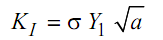
Several standard shapes enclosed in straight line boundaries or circular boundaries have been analysed both numerically and experimentally. In this text it is not intended to describe or discuss such methods but results will be taken from well known analytical and numerical methods. In these analyses the stress intensity factor of a crack is expressed in a convenient manner as
(KI is read as Kay one).
Here s is the gross stress without considering any change of area of cross-section, a is the crack length if crack is on the edge of half of the crack length if it is inside the boundary. Y is a non-dimensional stress intensity factor, also called calibration factor.
This factor may be expressed in terms of a polynomial containing terms that correlate crack length with some leading dimension of the body.
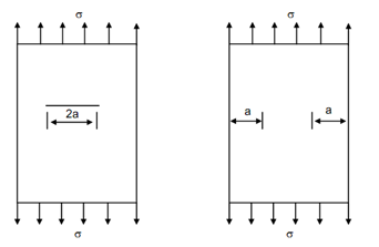
For a plate of width of W and a crack of length 2a in the centre under a tensile force, crack tip stress intensity factor is given by
K I = s[W tan (Pa/W)]1/2 ----------- (3)
where,
s = P/BW --------- (4)
B is the thickness of the plate and W is its width while P is the force acting normal to the crack line.
If the width of plate is much larger than a so that P a / W is small and tan P a / W = P a / W, then
 --------- (5)
Comparing this equation with Eq. (5.2) it is seen that Y = . Since the tip of the crack is far removed from the boundary the effect of boundary on crack tip stress field is non-existent.
Figure (b) also shows a plate but symmetrical cracks exist on edges. The length of each crack is a and load applied on edges of plate is again perpendicular to the cracks. The stress intensity factor of crack in this case cannot be unaffected by the boundary. It has been calculated as :
K I = sW 1/ 2 [tan P a /W + 0.7 sin 2P a /W]1/2 ---------- (6)
(a) (b)
Figure: Plate Samples with (a) Central Crack; and (b) Edge Cracks
It is obvious that if the plate is very wide, the crack tip KI of two symmetric edge cracks each of length a is 10% higher than that of a central crack of a length 2a, given by Eq. (5).
Yet another shape of interest to engineers is an edge cracked plate loaded in bending. Two types of bending loads can be applied as shown in Figure (a) and (b). In Figure (a), the load is applied perpendicular to the edge in the plane of the crack itself while the plane is supported at ends like a beam.
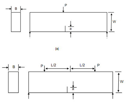
Figure: Three-point; and (b) Four-point Bend Specimens
In this state, the crack will be loaded both in Mode I and II. However, the effect of Mode II loading is minimal. Boundary collocation analysis of this configuration has been performed and KI determined in form of a polynomial. This configuration is also known as three-point bend sample. The crack tip stress intensity factor for this specimen is,
where,
Y1 = 1.93 - 3.07 (a/ W) +14.53 (a/ W )2 - 25.11 (a/W )3 + 25.8(a/ W )4 --------- (7)
The expression for non-dimensional stress intensity factor as given by Eq. (7) is applicable if S /W = 4 . The solution has been obtained for yet another situation in which S/W = 8 . This factor is
Y2 = 1.96 - 2.75 (a/ W ) + 13.66 (a/ W )2 - 23.96 (a/W )3 +25.22 (a/ W )4 --------- . (8)
The gross nominal stress, s, is the ratio of bending moment and modulus of section at central section of the beam.
i.e.,
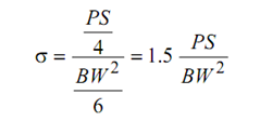
where, B is the thickness and W is the depth of beam specimen in Figure (a). If two concentrated loads, each equal to P, act symmetrically upon the beam as shown in Figure (b) such that each is at distance of L/2 from the mid-section then the crack plane will be free from shearing with bending moment being constant. The gross nominal stress
s = 3 P (S - L) /BW 2 .---------------(10)
The stress intensity factor in this case also has been determined as
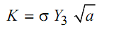
where,
Y3 = 1.99 - 2.47 (a/ W ) + 12.97 (a/ W )2 - 23.17 (a/W )3 +24.8 (a/ W )4 ------------ (11)
The configuration of specimen is also known as four-point bending. The magnitudes of Y1, Y2 and Y3 can also be read directly from Figure .From Eq. (2) and subsequent equation it is obvious that the unit of K1 will be
MPa √m or N/ mm2 √mm
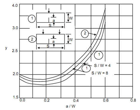
Figure: Non-dimensional Stress Intensity Factor Plotted as Function of a/W for Three Beam Specifications
Eq. (7) may be used to calculate stress intensity factor of edge crack in a plate under tensile load. This equation is applicable when loaded edges of plate are very much away from the crack line. However, Figure shows the same specimen with distance of loaded edges from the crack line defined as h. The broken line in this figure shows the variation of Y with a/W , for h/W = ∞ . This curve is basically represented by Eq. (6). The other two curves in Figure show the variation of Y with respect to a /W for h/ W =0.5 and h/ W = 1.0 .
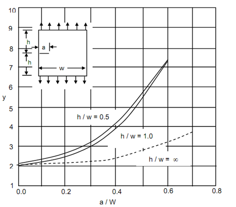
Figure: Non-dimensional stress Intensity Factor Plotted as Function of a/W for Edge Cracked Plane in Tension
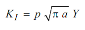
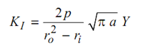
Figure shows the non-dimensional stress intensity factor of cracks on two sides of a circular hole in the middle of a plate under tensile loading (specimen shown in Figure 5.9). This is a typical case showing the effect of a curved boundary on crack tip stress intensity factor, when radius of the hole is comparable with crack length. The stress intensity factors of radial cracks on the inner and outer surfaces of a thick cylinder are depicted in Figures . These cracks would tend to become unstable under internal pressure p. The stress intensity factor for internal cracks is expressed as
 -------- (12)
where, p is the pressure on the inside of the cylinder. Figure shows Y as function of a / (ro – ri) for two symmetrically placed cracks. Figure 11 depicts variation of Y with a /ro – ri for a single crack on inner surface. In both cases the inner surface is jacketed and pressurized. Jacketing of inner surface does not pressurise the crack faces.
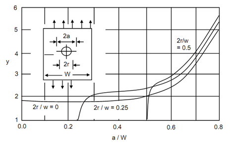
Figure: The Non-dimensional Stress Intensity Factor of Crack on Two Sides of a Crack Hole in the Middle of a Plate under Tensile Loading
Figure: Non-dimensional Stress Intensity Factor of Two Radial Cracks, Each of Length a on the Inside of Thick Cylinder
A crack on the outer surface of thick cylinder is placed under tensile stress which reduces from crack tip to the open end of the crack. Note this is opposite to the variation of tensile hoop stress in earlier two cases where stress decreases towards the crack tip.
Figure presents Y-values for crack on outside surface of thick cylinder. In this case, however, the SIF is given by following
 ...................(13)
The Hole is Pressurised with Inner Side Jacketed
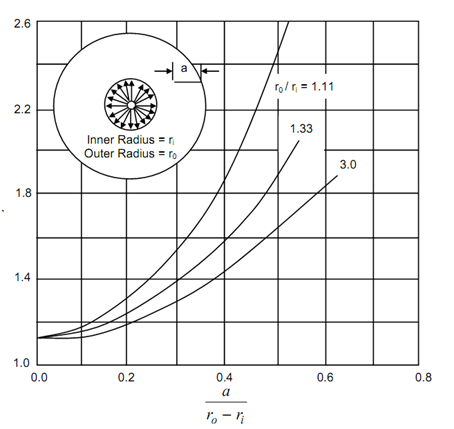
Figure: Non-dimensional SIF for Radial Crack on External Surface of a Thick Cylinder which is Pressurised from Inside
The Y variation like the ones of Figure gives a good opportunity for conducting experiments since Y reduces once the crack increases and hence a single sample can be used to obtain several observations.The results described here are a few of many which have been solved. The stress intensity factor of cracks at roots of gear teeth type blade joints in turbine rotors are of great interest. Similarly, designers may be interested in crack in rotating discs or thin pipes which could be fully across thickness or only on the surface.