Stress Intensity Factor Of A Crack
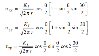
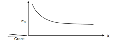
Stress distribution ahead of a crack has been analysed by application of mathematical theory of elasticity. The stress at crack tip, in the direction of y-axis is shown plotted in Figure. It is a well known fact that at crack tip the stress becomes infinite. Ahead of the crack the stress σyy (in the direction of y), σ found to be directly proportional to

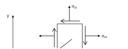
, where r and Φ are polar coordinates of any point in the close vicinity of the crack tip as shown in Figure . The constant of proportionality is defined as stress intensity factor of the crack. Stress intensity factor is denoted by K, with a suffix I, II or III to indicate Mode of crack face displacement. The crack in Figure is in Mode I and the state of stress depicted there may be expressed as follows σ xx (in the direction of x) and shearing stress are
 --------------- (1)
where KI is Mode I stress intensity factor. (The suffixes I, II and III should be read as “one”, “two”, and “three”. Thus KI is read as “K one”.) The equations described above are applicable in very close vicinity of crack tip, i.e. when r ≤ 0.02 X crack length. It can be seen that σyy is the higher of two tensile stresses everywhere except for Φ = 0, when σxy vanishes and σxx and σyy become equal creating a situation of equibiaxial tension. Absence of σxy in the line of crack makes it impossible for plastic deformation to take place and hence crack can propagate or extend to brittle manner.

Figure: Variation of σyy ahead of a Crack. σyy Tends to be Infinity at Crack Tip

Figure: State of Stress in the Vicinity of the Crack Tip
The stress intensity factor of a crack is a function of applied stress, length of the crack and geometrical configuration of the cracked body. Thus, it is a single factor which can define state of stress around crack tip completely.