Fuel Injector Plungers:
The motion of the injector rocker arm (not show) is transmitted to the plunger by the injector follower which bears against the follower spring. As the plunger moves downward under pressure of the injector rocker arm then a portion of the fuel trapped under the plunger is displaced within the supply chamber through the lower port until the port is closed off through the lower end of the plunger. A fuel trapped under the plunger is after that forced up by the central bore of the plunger and back out the upper port until the upper port is closed off through the downward motion of the plunger. Along with the upper and lower ports both closed off, the remaining fuel below the plunger is subjected to a rise in pressure by the downward motion of the plunger.
While enough pressure has built up, an injector valve is lifted off its seat and the fuel is forced by small orifices in the spray tip and atomized within the combustion chamber. The check valve, mounted in the spray tip, avoids air in the combustion chamber from flowing back within the fuel injector. The plunger is after then returned back to its original position through the injector follower spring.
In the return upward movement of the plunger, high pressure cylinder within the bushing is again filled along with fresh fuel oil through the ports. A constant circulation of fresh, cool fuel by the injector renews the fuel supply inside the chamber and helps cool the injector. The fuel flow also professionally removes all traces of air which might otherwise accumulate in the system.
The fuel injector outlet opening, through that the excess fuel returns to the fuel return manifold and then back to the fuel tank, is adjacent to the inlet opening and holds a filter elements exactly the same as the one on the fuel inlet side.
In addition to the reciprocating motion of the plunger, the plunger could be rotated during operation around its axis by the gear in which meshes along with the fuel rack. To metering the fuel, an upper helix and a lower helix are machined in the lower categories of the plunger. A relation of the helices to the two ports in the injector bushing modifies along with the rotation of the plunger.
Changing the position of the helices, through rotating the plunger, retards or advances the closing of the ports and the starting and ending of the injection period. At the similar time, it increases or decreases the amount of fuel injected within the cylinder. Figure describes the several plunger positions from NO LOAD to FULL LOAD. Along With the control rack pulled all the way (no injection), the upper port is not closed through the helix until after the lower port is uncovered.
Conclusion, within the rack in this position, all of the fuel is forced back inside the supply chamber and no injection of fuel takes place. Within the control rack pushed all the way in (full injection), the upper port is closed in a while after the lower port has been covered, therefore generating a maximum effective stroke and maximum fuel injection. By this no-injection position to the full-injection position (full rack movement), a contour of the upper helix advances the closing of the ports and the starting of injection.
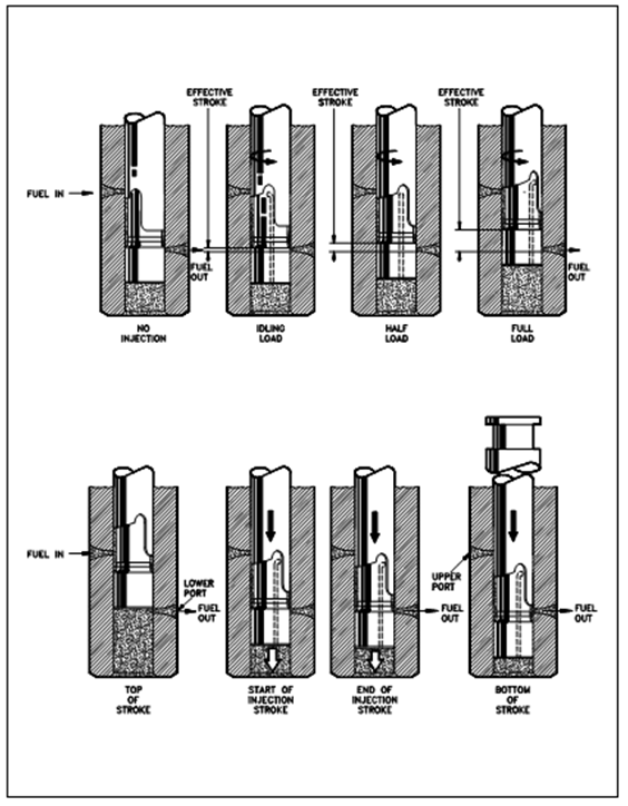
Figure: Fuel Injector Plungers