Cam and follower mechanism:
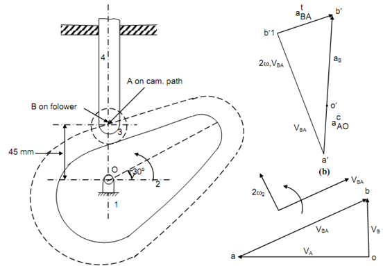
A cam and follower mechanism is illustrated in Figure (a), the dotted line specify the path of point B (on the follower). The cam rotates at 100 rad/s. Draw the velocity & acceleration diagram for the mechanism and find the linear acceleration of the follower. Minimum radius of cam = 30 mm & maximum lift = 35 mm.

(a) (c)
Solution
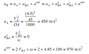
Linear velocity of point A that is on the cam, VA = ω × OA.
or, 
VB = VA + VBA
(a) Suppose suitable scale say 1 cm → 1 m/s.
(b) Plot velocity of A by drawing a line perpendicular to OA from pole o. It defined by oa.
(c) From the point o, draw a line parallel to motion of follower to define direction of velocity of follower.
(d) Draw a line from the point 'a', parallel to the motion of B that is parallel to the tangent at cam profile to meet line demonstrating direction of velocity of follower at the point b. ob signify velocity of follower in magnitude & direction
VB = 1.75 m/s and
VBA = 4.85 m/s
Velocity polygon is shown in Figure (b).
Acceleration Diagram

(a) Choose suitable scale say 1 cm → 200 m/s.
(b) Plot aA by drawing a line parallel to OA from o′ & length equivalent to 2.25 cm.
(c) Now plot acor perpendicular to profile of cam and length equivalent to 4.85 cm. It is defined by a′ b′1.
(d) Now draw a line perpendicular to a′ b′1 to signify direction of  .
.
(e) Draw another line from o′ to define direction of motion of B to meet direction of at b′. o′ b′ shows acceleration of B in magnitude and direction.
aB = 3 × 200 = 600 m/s2
The acceleration polygon is illustrated in Figure (c).