Deflection of Spindle Axis because of Bending
To compute the deflection of the spindle nose due to bending, one should establish a proper design diagram. The subsequent guidelines may be utilized in this regard.
(1) Whether the spindle is supported on a single anti-friction bearing at each end, it may be presented as a simply supported beam, and
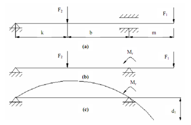
(2) If the spindle is supported in a sleeve bearing, the supported journal is analyzed like a beam on an elastic foundation; for the aim of the design diagram the sleeve bearing is replaced through a simple hinged support and a reactive moment Mr acting at the middle of the sleeve bearing.
The reactive moment is expressed as:
Mr = C. M
Where M = bending moment at the support, and
C = constant = 0 for small loads & 0.3 to 0.35 for heavy load.

Figure: Effect of Various Forces on Spindle
Figure (a) displays schematic diagram of spindle. Figure (b) depicts the design diagram of the spindle and figure (c) demonstrates deflected axis of the spindle.
Consider the spindle displayed in Figure (a). By changing the rear ball bearing by a hinge and the front sleeve bearing through a hinge and reactive moment Mr, the spindle can be reduced to the design diagram as displayed in Figure (b). The deflection at the free end of the beam (spindle nose) can be ascertained by Macaulay's method and is found out to be
Equation

In which
E stands for Young's modulus of the spindle material
Ia is average moment of inertia of the spindle section. The deflection of the beam is displayed in Figure (c).