Design of Roof Truss Bearings:
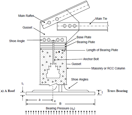
If the steel roof truss is supported on steel columns, they are joined to the latter by the usual beam column type of connections, which have been already discussed in earlier sections. If that are supported on masonry columns a suitable bearing plate is used which is anchored to the masonry by suitable anchor bolts. The roof truss is connected to the bearing plate through shoe angles (Figure (a)).
Shoe Angles and Base Plate
An area of the bearing plate A is given by
A = R/σ p
where, R = Vertical reaction at the truss bearing,
σp = Allowable bearing stress in concrete or masonry (may be taken as 4 N/mm2), and
A = B × L = Width × Length of bearing plate.
To denote the thickness of the bearing plate t1, we have to equate the moment of resistance of the plate (MR) to the bending moment (M) due to actual bearing pressure along the section x-x (Figure (b)).
Here MR = σbs .Z = σbs Lt12/6
where σbs = allowable bearing stress in steel plates = 185 N /mm2
But M = σ p ⋅ L ⋅a2/a
as MR = M
we have σbs Lt12/6 =σp L (a2/a)
This gives 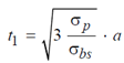
Substituting σ p =4 MPa and σbs =185 MPa
we get t1 ≈ 0.25 a
The shoe angles are designed to accommodate the number of rivets required to transmit the maximum support reaction. Normally double angle 75 × 75 × 6 mm are used as shoe angle.