Wind Load Analysis:
Next, the roof truss is analysed for wind forces, with the wind blowing from the right. This is shown in Figure(d). The reaction and member forces are calculated as indicated above which may be verified.
The above results are tabulated in Table.
Table: (All Values in Newtons)
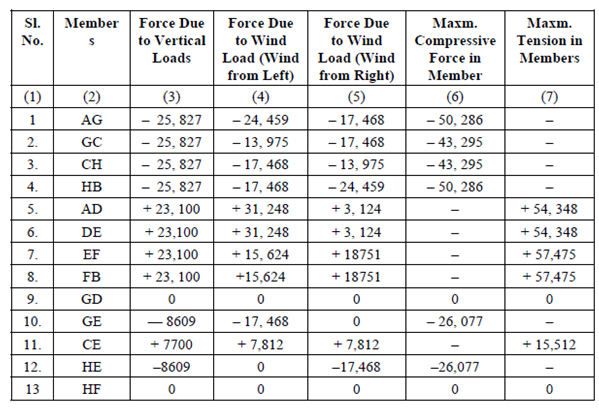
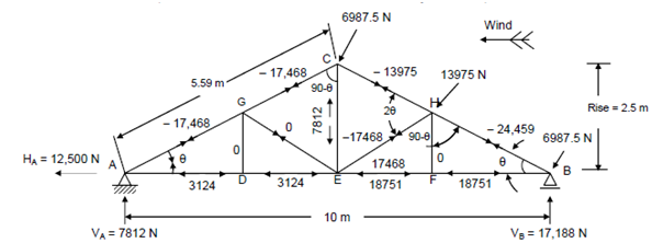
Figure : Wind Load Analysis
Design
Looking at Table 7, columns (6) and (7), it is at once obvious that which member is to be designed for what magnitude (and type) of force.
The rafter members AG and GC have different maximum compressive forces in them (50,286 N and 43,295 N). But as it will not be economical to have two separate sizes of members for each panel, as the cost of cutting and joining them will be more than having a single continuous piece (with a difference of perhaps a few kg of metal) the entire principal rafter AC (and CB) will be designed for the greater of the two loads, i.e. 50,286 N (Compression).
Similarly, the principal tie ADEFB will be designed as one member for the bigger tensile force of 57,475 N (Tension).
The sloping members GE and HE will be identical, designed for a compressive force of 26,077 N or the vertical tie CE will be designed for a maximum tension of 15,512 N. Since the vertical ties GD and HF do not carry any load just a nominal member of smallest size might be used.