Example of Design of Angle Iron Purlins:
Example
Design an angle iron purlin for a steel roof truss given the subsequent:
Span of roof truss = 15 m
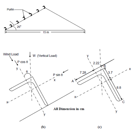
Slope = 26o
Spacing of roof truss = 5 m
Number of purlins along the roof truss = 7
Wind load on roof truss = 1.12 kN/m2
Dead load from roof covering = 0.50 kN/m2
Solution
Figure
Assume self weight of purlin = 70 N/m2
Weight of roof covering (AC sheets) = 160 N/m2
Live load = (0.75 - 0.02) × (26o - 10o) = 0.43 kN/m2 = 430 N/m2
Total vertical load per m2 of plan area = 660 N/m2
Horizontal plan area for each purlin = (15/2)/6 × 5 = 6.25 m2
∴ Total load on each purlin, W = 660 × 6.25 = 4125 N
Component of load parallel to y-axis of purlin
= W cos 26o = 4125 cos 26o = 3708 N
Component of load parallel to x-axis of purlin
= W sin 26o = 4125 sin 26o = 1808 N
Wind load on roof truss = 1.12 kN/m2 = 1120 N/m2 parallel to y-axis of purlin.
Sloping area for each purlin = 7.5/6 sec 26o × 5 = 6.95 m2
∴ Total wind load on each purlin = 1120 × 6.95 = 7784 N
∴ Total load parallel to y-y axis, Wy = 3708 + 7784 = 11492 N
Total load parallel to x-x axis, Wx = 1808 N
Bending moment parallel to y-y axis, M y = Wy ⋅ L/10
= (11492 × 5)/10 = 5746 Nm= 5746 × 103 Nmm
Bending moment parallel to x-x axis, M x =Wx ⋅ L/10
= (1808 × 5)/10 = 904 Nm = 904 ×103 N mm.
Approximate depth = L /45= 5000/45= 110 mm
Approximate width = L/60 = 5000/60 =85 mm
Adopt 125 × 95 × 6 mm angle having the following properties
Area = 12.86 cm2; Ixx = 203.2 cm4; Iyy = 102.1 cm4
The angle is placed as shown in Figure 5(b) such that the smaller leg is at the top and the longer leg is placed such that the corner B is placed upwards. The major axis y-y is perpendicular to the principal rafter. It is important to note that such an orientation of the angle leads to smaller compressive stresses. As permissible stresses in compression are always less than that in tension such a placement of the angle is the best suitable one.
Any other orientation will lead to larger bending stresses at the corner A, B, and C.