Graphical Method for Profile of Flat Form Tool
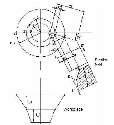
The graphical method profile of flat form tool is displayed in diagram. The graphical method is explained as follows:
(1) Draw profile of the workpiece in lower left corner.
(2) Project basic points on the axis I-I that is 1′, 2′, 3′ etc. and form point O as a centre. Draw circles corresponding to radius r1, r2, r3 passes via 1′, 2′, 3′ correspondingly.

Figure: Graphical Method of Determining the Profile of Flat Form Tool
(3) Assign proper value of α, ϒ. Determine outer diameter and centre of flat through point form tool.
(4) By point 1, 2, 3, draw a line parallel to the flank.
(5) To construct the cross-section of the tool perpendicular to the flank (set N-N), draw line LL which is perpendicular to flank.
(6) From the line LL, we lay off the lengths l1 and l2, as the dimensions of the tool profile measured along with the workpiece are equal to the corresponding axial dimensions of the workpiece.
(7) At lengths l1, and l2 draw lines parallel to LL and attain point of intersection as 1″, 2″, and 3″, which on joining gives profile of form tool.