Steps for Design:
The subsequent steps are to be taken while designing compound compression members with lacing:
(a) Select a suitable arrangement of structural members (e.g. one as shown in Figure 10). The size of the open columns usually lies between 1/9 to 1/14 of the column length.
(b) Supposing a reasonable value of λ, find the corresponding σac from Table 2 and find the total area of the column A= P/ σac.
From your assumed value of λ, also find rmin = leff / λ.
(c) From the total area A, find the individual area of each element and select suitable structural sections. From the tabulated values of rx′x and ry′y and A′, of each component find rxx and ryy of the compound column, so that both are approximately equal. In this, help of Table 3 may be taken.
(d) Finally, for the selected structural sections, calculate the exact A, rmin, leff, λmax etc. From the last data find the corresponding σac from Table 2 and check up with your assumptions in step (b). If there is a discrepancy repeat the process.
(e) Select the angle of inclination of the lacing bars (40o < θ < 70o; generally 45o), their maximum spacing, width, thickness, etc. (If the single-lacing system gives a large value of l′ such that θ > 70o, then adopt double-lacing system.)
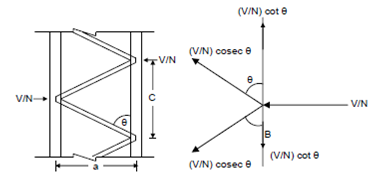
(f) Design the lacing for a transverse load of V = P/40. Divide total V between the numbers (N) of lacing systems provided. The forces (compressive or tensile) in the lacing bars will be V/ N cosec θ as shown in Figure.

Figure: Forces Acting on Lacings and Tie Plate
(g) End tie plates are given at end of the column and are designed as battens
Bending moment in tie plate = VC/2 N, and
Shear force = VC/aN
where, C = Spacing of lacings, and
a = Centre to centre length of tie plate.