Illustrative Example on the Design of Sanitary Sewer System
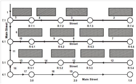
Design a system of sanitary sewers for the given area shown in the Figure 6.3 with the following details:
(a) Population density: 300 persons/hectare.
(b) Water supply: 250 litre per day/head (ultimate).
(c) Maximum rate of infiltration: 20,000 litre per day/hectare.
(d) Minimum depth of cover to be provided over the crown of the sewer: 1.0 m.
(e) Minimum velocity in sewer at peak flow : 0.6 m per second.
(f) Maximum velocity in sewer : 6.0 m per second.
(g) Minimum size of the sewer : 150 mm.
(h) Waste water reaching sewers : 90% of water supply.
(i) Peak flow : 3.5 × Average flow.

Figure 3: Sanitary Sewer System
Solution
(a) Place the lines on map to represent proposed sewers with arrow indicating assumed direction of flow.
(b) Locate the manholes giving each an identification number as described in the nomenclature of this unit.
(c) Determine the area tributary to each lateral.
(d) Prepare a table showing computational details of each sewer between manholes.