SS Beams with Triangular Load:
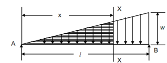
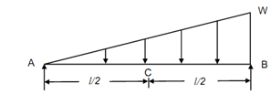
Figure illustrates a simply supported beam with distributed load which uniformly increases from 0 at A (x = 0) to w/unit length at B (x = l). Therefore, to load diagram appears as a triangle. Actually the total load = area of the triangle = (½) wl and at any section X-X at a distance x from A the rate of loading shall be wx/ l , so that the load of shaded triangle = (1 /2)(wx/l) x = (1 /2)wx . This load will act at a distance of 2x/3 from (centroid of triangles). The sum of the reactions (RA + RB) shall be equal to the load of entire triangle, that is
∑ y = 0
or,
RA + RB = (½) × l × w = (wl/2)

SS Beam with Triangular Load
Taking moments around A,
wl /2× 2l/3 = R B × l
R B = wl/3 (↑) ----------- (38)
From Eqs. (9.37) and (9.38),
R A = w l /6 (↑) ------------ (39)
Let a section X-X at distance x from A,
Intensity of load = (wl /x)
M = R A x - (½) (wl/x) . x . (x/3)
= wl x/6 - w x3/6l
The governing equation for deflection is following
EI (d 2 y/ dx2) = M = wl x/6 - w x3/6l
Integrating the Eq. (41), we can obtain
EI (dy/ dx) = w l x2/12 - w x4 /24l + C1
EIy = wl x3 /36- w x5/120l + C1 x + C2
The constants C1 & C2 may be found from the boundary conditions. The boundary conditions are following :
at A, x = 0, y = 0
at B, x = l, y = 0
Applying the BC (1) to the Equation (43), we can obtain C2 = 0.
Applying the BC (2),
0 = wl 4 /36- w l 4 /120 + C1 l
C1 = (wl 4 /360 l )[3 - 10] = - 7 wl3/ 360
The slope & deflection equation shall be :
EI (dy /dx)= w l x 2 /12-w x4 /24l - (7 /360)w l 3
EIy = wl x3/36-w x5/120 l- (7/360) w l 3 x
Slope at A, (x = 0)
( dy/dx) A= θA =- 7 w l3/360 EI
Slope at B, (x = l)
EI (dy/dx) B= EI θB = w l3 /12- w l3 /24 - (7 /360 )w l 3
= wl 3/360 [30 - 15 - 7] = wl 3/45
∴ θ B = wl3/ 45 EI
Slope at mid-span, (x = l/2) .
EI (dy/dx) = EI θC = wl3 /48 - wl 3 / (24 × 16) - (7/360) w l 3
= (wl3/24 × 16 × 15 )[30 - 15 - 7 × 16] = -67 wl 3/ 5760
∴ θC = -67 wl 3/5760EI
Deflection at centre, (x = l /2) .
EI y = (wl4 /(36 × 8) ) -(w l4/(12 × 32) - (7 /360 × 2)w l 4
= (wl 4/630 × 32) [40 - 3 - 7 × 16] = - 71w l 4 /11520
For maximum deflection,
dy / dx = 0
From Eq. (42),
0 = wl x2 /12 - w x4 /24 l - (7/360) wl3
⇒ 0 = 30 l 2 x2 - 15 x4 - 7 l 4
⇒ x4 - 2 l 2 x2 + 7/15
∴ x = 0.5193l
From Eq. (43),
EI ymax = wl /36 (0.5193l ) 3- w/120 l - (0.5193l )5
-(7/360 × 2 )wl 3 (0.5193l )
= (wl 4 /360) [14 - 0.11 - 3.64] = wl 4 / 153
∴ ymax =- wl 4 /154

(a) Beam

(b) Slope Diagram

(c) Deflection Diagram
Figure