The superheterodyne
The superheterodyne uses one or more mixers to convert an incoming signal, regardless of the frequency of it, to an identically modulated signal at another, constant frequency. The signal frequency can be heterodyned once, twice, or even 3 times. Thus, you may hear of a single-conversion, double-conversion, or triple-conversion superheterodyne receiver.
A single-conversion superheterodyne
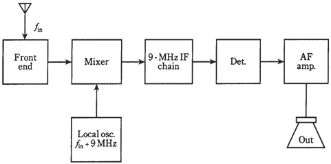
Thetheblock diagram of a single-conversion receiver is given in the figure given below

Figure--A single-conversion superheterodyne receiver.
The incoming signal 1st passes through a sensitive, tunable front-end amplifier. The tuning range of this amplifier should be sufficient to cover all desired reception frequencies fIN.
The 2nd stage is a mixer/LO combination. The LO has a variable frequency which tunes over the received signal range plus 9.000 MHz. The LO frequency control is the main tuning control for the entire receiver. The LO tuning might track along with tuning of front end, or the front end might tune independently by means of a separate preselector control. The mixer output is at 9.000 MHz, no matter what is incoming signal frequency.
The intermediate frequency
The 9.000-MHz mixer output signal is known as intermediate frequency (IF) of the superhet. This signal has same modulation waveform, and the same bandwidth, as the incoming signal. The only difference is that it may be upside down; LSB would be changed to USB, or sense of FSK will be reversed. But this is the inconsequential difference in so far as it has no effect on quality of received signal.
The IF is simple to process as its frequency never changes. Several IF amplifier stages, the with filtering, give the best possible sensitivity and selectivity. This part of the receiver is the IF amplifier chain or IF chain.
Image rejection
In the superhet of the figure given below, the LO frequency, fLO, is above fIN. The difference is always 9.000 MHz. Therefore, if fIN = 3.510 MHz, then fLo = 3.510 + 9.000 MHz = 12.510 MHz. And if fIN = 15.555 MHz, then fLO = 15.555 + 9.000 MHz = 24.555 MHz. The IF is obtained by difference mixing. The9. 000-MHz IF is the signal at fLO – fIN.
However, there is another possible frequency which can mix with the LO signal to generate a 9.000-MHz output. That is difference fIN − fLO. Suppose you have LO set at fLO = 12.510 MHz, so that the receiver hears signals at fIN = 3.510 MHz. If the signal comes on at fLO + 9.000 MHz = 12.510 + 9.000 MHz = 21.510 MHz, and if this signal gets through front end of receiver, then it will mix with LO signal to produce a false signal at 21.510 − 12.510 MHz = 9.00 MHz. This is known as image signal.
Assume that you set the LO at fLO = 24.555 MHz, so that receiver hears signals at fIN = 15.555 MHz. If a signal appears at fLO + 9.000 MHz = 24.555 + 9.000 MHz = 33.555 MHz, then you will hear it in 9.000-MHz IF chain as an image signal.
Clearly, you do not want the receiver to hear image signals; you want it to receive at the desired fIN. A good preselect or will offer image rejection. This is helped along by choosing a high IF, such that the image frequency, fIMAGE, is quite different from fIN. That way, the tuned circuit in front end has an easy time separating real thing from the impostor.
Multipleconversion
The other way to improve image rejection is to convert 9.000-MHz (or whatever frequency) 1st IF to a lower IF, known as the 2nd IF. This is generally a frequency between around 50 kHz and 500 kHz. A standard 2nd IF is 455 kHz. The resulting receiver is a double conversion superhet.
At times the 2nd IF is converted to a still lower frequency, called as 3rd IF, usually 50 kHz. This is a triple-conversion superhet.
The basic advantage of using double or triple conversion, besides superior image rejection, is fact that low IFs is easily filtered to provide superior adjacent- channel rejection.Low IFs are not practical with single-conversion receivers, as fIMAGE would be too close to fIN, and the front end could not sufficiently differentiate between them. This problem would be worst at highest frequencies fIN.
Detector and audio/video amplifier
Once if the IF signal has been filtered and amplified, it passes through the detector. This is usually a product detector for CW, FSK, and SSB, a ratio detector or PLL for the FM, and an envelope detector for the AM.Following detector, a DSP circuit can be used. This further enhances S/N ratio, minimizing number of printer or display errors, or clarifying audio or video.
Finally, the audio/video amplifier is used to boost level to whatever is required to drive speaker, monitor, teleprinter, or instrumentation at the receiver output.