Fundamentals of Cyclic Voltammetry:
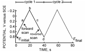
It consists of cycling the potential of an electrode which is immersed in an unstirred solution of the electroactive species and then measuring the resulting current. A potential of this working electrode is controlled versus a reference electrode like as a saturated calomel electrode (SCE) or a silver/silver chloride electrode (Ag/AgCl).An controlling potential that is applied across these two electrodes can be considered as excitation signal. The excitation signal for CV is a linear potential scan with a triangular waveform as given in Figure. This triangular potential excitation signal sweeps the potential of the electrode between two values, many times known as the switching potentials. The excitation signal in Figure causes the potential first to scan negatively from +0.80 (initial potential) to - 0.20 V (EF final potential) versus SCE at which point the scan direction is reversed, resulting a positive scan back to the original potential of +0.80 V (Ei). The scan rate as reflected by the slope is 50 mV per second as shown in Figure. A second cycle is indicated by the darked line. One or multiple cycles can be used.

Figure: Typical excitation signal for cyclic voltammetry-a triangular potential waveform with switching potentials at 0.8 and -0.2 V versus SCE