Voltages Across Series Resistances:
In a series circuit, the voltage is splitted up among the components. The total sum of the potential differences across each resistance is equivalent to the dc power-supply or battery voltage. This is always true, no matter how big or how small the resistances and whether or not they are all the same value.
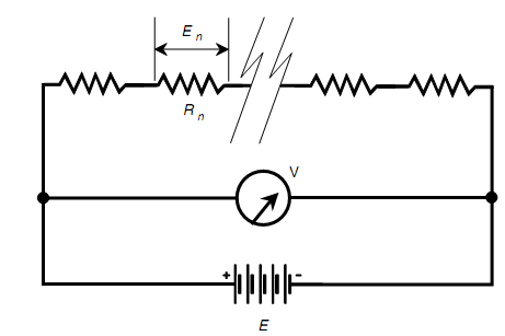
When you think about this for a moment, it is easy to see why this is true. Look at the schematic diagram as shown in figure below. Each resistor carries the same current. Each resistor Rn has a potential difference En across it is equivalent to the product of the current and the resistance of that specific resistor. These En values are in series, like cells in a battery, therefore they add altogether. What if the En values across all the resistors added up to something more or less than the supply voltage E? Then there would be a "phantom emf" anywhere, adding or taking away voltage. Though, there can be no such thing. An emf cannot come out of nowhere.

Look at another way. The voltmeter V in Fig. shows the voltage E of the battery since the meter is hooked up across the battery. The meter V also shows the sum of the En values around the set of resistors simply as the meter is connected across the set of resistors. The meter says the similar thing whether you think of it as measuring the battery voltage E or as measuring the sum of the En values around the series combination of resistors. And hence, E is equal to the sum of the En values.
This is a basic rule in series dc circuits. It also holds for general utility ac circuits almost all the time.
How do you find the voltage across any specific resistor Rn in a circuit such as the one in figure as shown below? Remember Ohm's law for finding voltage: E = IR. The voltage is equivalent to the product of the current and the resistance. Remember, too, that you should use volts, ohms, and amperes whenever making computations. In order to find the current in the circuit I, you require knowing the total resistance and the supply voltage. Then I = E/R. At first find the current in the entire circuit; then find the voltage across any specific resistor.
PROBLEM:
In the given figure, assume that there are 10 resistors. Five of them have values of 10 ohms, and the other 5 have values of 20 ohms. The power source is 15 V dc. Determine the voltage around one of the 10-ohm resistors? Across one of the 20-ohm resistors?
SOLUTION:
First, find the total resistance: R = (10 x 5) + (20 x 5) = 50 + 100 = 150 ohms. Then find the current: I = E/R = 15/150 = 0.10 A. This is the current through each of the resistors in the circuit. When Rn = 10 ohms, then En = I (Rn) = 0.10 x 10 = 1.0 V
When Rn = 20 ohms, then En = I (Rn) = 0.10 x 20 = 2.0 V
You can check to see whether all these voltages sum up to the supply voltage. There are 5 resistors with 1.0 V across each, for a total of 5.0 V; there are also 5 resistors with 2.0 V across each, for a total of 10 V. Therefore the sum of the voltages across the 10 resistors is 5.0 V +10 V = 15 V.