Synchronous Counters:
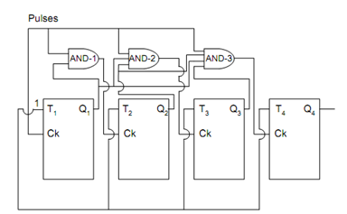
In Synchronous counters the Flip Flops are triggered in synchronism with the clock unlike the ripple or asynchronous counters. There are some inherent problems with the ripple counters as each Flip Flop has a time delay. The total time delay of a ripple counter is the summation of time delays of each Flip Flops, which restrict the highest operating frequency of counters. The Synchronous counter illustrated in Figure has overcome this problem by some type of parallel operation. The truth table is the same as in Table and the waveform chart is also the same as depicted in Figure. Let us attempt to understand the operation of these binary counters. Each of the Flip Flop is a T-type Flip Flop with the input T tied to 1 and therefore it acts as toggle Flip Flop. The Clock input has some modifications for parallel operation as illustrated in Figure. Whenever Q1 is high, AND-1 output is high; a clock pulse is passed through the clock input of second Flip Flop. Therefore Q2 modify its state at the negative transition of pulse 1, 3, 5 and 7. Note down that these Flip Flops are negative triggered Flip Flops. The AND-2 output is high only when Q1 and Q2 are high thereby enabling the third Flip Flop hence the Q3 shall change state at the negative transition of pulse number 3 and 7 only. If we try to write the Binary numbers, which are built up of values of Q1, Q2, Q3 and Q4 for different time periods from the waveform chart of Figure, we shall get the Truth Table which is basically a upward binary count for mod-16 parallel counter. Note down that the problem of propagation delay has been overcome in such counters since all of the Flip Flops changes its state at the same time or in synchronism with the system clock pulse. The waveform chart and truth table for the synchronous counter is the same with the previous ripple counter only that now we are modifying the states of the Flip Flops simultaneously or in synchronism with system clock.

Figure: Four Element Synchronous Counter