Stability of Spring-controlled Governors:
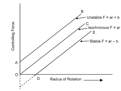
Given figure shows the controlling force curves for isochronous, stable and unstable spring controlled governors. The controlling force curve is about straight line for spring controlled governors. As controlling force curve shows the variation of controlling force 'F' having radius of rotation 'r'. Therefore, straight line equation may be following,
F = ar + b; F = ar or F = ar - b . . . (12.30)
here a and b are constants. In the above equation b can be +ve, or -ve or zero.

These three cases are as:
(1) We know that for a constant governor, the ratio F/ r should increase as t increases. Therefore the controlling force curve DE for a firm governor should intersect the controlling force axis (that is. y-axis) below the origin, when generated. Then the equation of the curve shall be of the form
F = a . r - b or F / r = a -( b/ r) . . . (12.31)
As r increases tan φ raises.
(2) In the above equation if b is zero then the controlling force curve OC shall pass through the origin. The ratio F/r shall be constant for all radius of rotation and therefore the governor shall become isochronous. Therefore for isochronous, the equation shall be
F = ar or F /r= a = constant . . . (12.32)
(3) If b is + ve, then controlling force curve AB shall intersect the controlling force axis (that is y-axis) above the origin. The equation of the curve shall be
F = ar + b or F/r = a + (b/r) . . . (12.33)
Since r increases, speed increases, F /r or tan φ fall down. Therefore this equation cannot show stable governor but unstable governor.