Support bending moments:
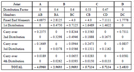
In Table, the first row denotes the 'joints' which in this case are the four support points A, B, C, D. Further two rows denote the 'distribution factors' and names of the members meeting at the joint. At end supports A and D, there is one member each (e.g. AB and DC); at the intermediate supports B and C two members' one from either side meet (e.g. at B we have BA, BC and at C, we have CB, CD). As the joints A and D are fixed no distribution is to be done at this point and the DFs are zero.
At joint B, the distribution factors for members BA and BC which are 0.4 and 0.6 as calculated above are noted. Same, at joint C, the distribution factors for the members CB and CD that are 0.53 and 0.47 are noted. A double line at this point is given showing the beginning of the process.
In the next row, the fixed end moments for each member as calculated previously in step (1) are remembered. A first moment distribution for the unbalanced joint moments is then done in the next row. Below member AB at joint A, we shall write 0 as there is no distribution done here. Next at the joint B, we have fixed end moment + 2.8125 in member BA and - 4.0 kNm in member BC. Thus, there is an unbalanced moment of + 2.8125 - 4.0 = - 1.1875 kNm. The balancing moment (M) will be equal in magnitude but opposite in sign, i.e. + 1.1875 kNm. Now this moment has to be distributed in the ratio of 0.4: 0.6 ratio in the two members BA and BC.
∴ Balancing moment for BA = + 1.1875 × 0.4 = + 0.475 kNm
and Balancing moment for BC = + 1.1875 × 0.6 = + 0.7125 kNm.
These two moments are noted in their respective columns in the row '1st Distribution'. The same process is done at joints C and D which can be verified. After completing the first distribution, half the moments at each end are to be carried over to the other end as explained above. Hence in the first carry over operation for member AB as the end A had 0 moment corrections, therefore, carry over to end B will be 0 and end B has +0.4750 kNm correction so + 0.4750/2 = + 0.2375 is carried over to end A. This is shown by a pair of arrows.
Similar carry overs are done for members BC (CB) and CD (DC).
As you cannot stop after a carry over a second distribution must be done this is shown in the next column. Therefore, two cycles of distributions are completed. In the table shown two more cycles (that is four distributions) of operations are performed. After the fourth distribution we see that the correction moments have become less the 0.05 kNm. Hence the moment distribution process is stopped and all the moments in the same vertical line are algebraically added. This gives the final bending moments at each joint (member - end).
In member AB: the left hand end A is acted upon by a negative moment - 4.5960 kNm which is anticlockwise and, therefore, causes a hogging (or negative) bending moment. At end B we have a positive moment + 2.9693 kNm which is clockwise and since it is acting at right hand end it will be again hogging (or negative) BM. Through extending the above argument we see that all the support bending moments are hogging (i.e. negative) BM.