Continuous Beam with Hinged End Supports:
In the above example, the end supports of the continuous beam are fixed, hence no distribution is required there. However, in the case of end supports being simply supported (hinges) the bending moments will be zero and at this point the fixed end moments will have to be fully redistributed. This is explained in the next example.
Example
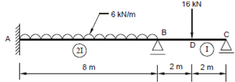
Draw the BM and SF diagrams for the continuous beam ABC shown in Figure 11, using moment distribution method. The moment of inertia in span AB is doubles that of BC.

Solution
Fixed End Moments
MFAB =- (6x82)/12 = -32 kNm. MFBA = +32
MFAB =- (6x4)/8 = -8 kNm. MFCA = +8 kNm
Distribution Factors
At joint A, DF = 0, since it is fixed.
At joint B, there are two member = K BA = 2 I/8 and K BC = I/4
∴ (DF )BA = (2I/8)/(2I/8)+(I/4) =0.5; (DF )BC = (I/4)/(2I/8)+(I/4) =0.5;
At joint C, Distribution Factor = 1, because it is hinged.
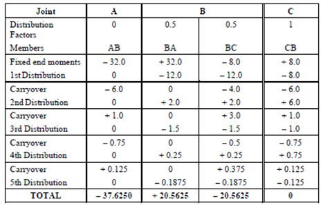
The procedure of moment distribution is next carried out in the table below and does not need any further explanation.
Table 2
