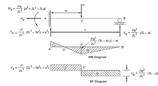
Bending moment and shearing force:
Hence, the downward deflection Δ0 at the end B is given by (using second set)
Δ0 = C.l + D = - Pa2 l/2 EI + Pa3/6 EI =- Pa2/6 EI (3L - a)
Next considering the case of Figure 4(b) when the cantilever is acted upon by the reactive force VB.
BM at any distance x from A is given by M = VB (L - x)
Or d2y/ dx2 = VB/EI (L - x)
On integration
Slope dy/dx = VB/EI (Lx-x2/2) +Q
Deflection y= VB/EI ( L(x2/2-x3/6))+Qx+R
The value of the arbitrary constants are determined by the support conditions at fixed end A; namely, when x = 0, we have
dy/dx = 0 and y = 0.
Substituting these conditions in the above two equations, we get
Q = 0 and R = 0.
∴ dx/dy = VB/EI (Lx -(x2/2))
Y=VB/EI (L(x2/2-x3/6))
Hence, calculating the upward deflection Δ′ at the end B, we get
Δ′ = VB/EI(L3/2-L3/6) = VBL3/3EI
Now as a roller support at D is rigid there is no vertical deflection or Δ0 + Δ′ = 0 which is the required equation of compatibility in this case.
Substituting, we get
- Pa2/6EI(3L-a)+VBL3/3EI
Or VB=Pa2 /2L3(3 L - a)

Next applying the conditions of static equilibrium, we get the support reactions at A,
∑ H = 0 gives HA = 0
∑V = 0 gives VA + VB = P giving
VA = P/2L3 [2L3-3a2 L + a3 ]
∑ M = 0 gives
MA = Pa/2 L2 [3 La - a 2 - 2L2 ] = -Pa/2 L2 [a 2 + 2L2 - 3La]
The bending moment and shearing force diagrams are shown in Figure. (You should verify the values given yourself.) Between A′ and D′ the BM diagram is negative and between D′ and B′ it is positive.
SF is negative between A′ and C′, and is positive between C′ and B′.