Basic Cycle for Reciprocating Compressor:
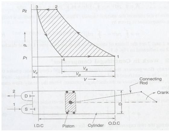
The p-v diagram of a reciprocating compressor is shown in the given fig along with the skeleton diagram of the cylinder & piston mechanism.
While the piston is in the extreme left position of the inner dead centre (IDC), the volume occupied via the gas is Vc = V3 called up clearance volume, that means the volume among the piston & cylinder head. Since the piston moves outward, the clearance gas expands to 4, while the pressure inside the cylinder is equivalent to the pressure at the suction flange of the compressor. Since the piston moves further, the suction valve S opens & the vapour from the evaporator is sucked up in till the extreme right position of the outer dead centre (ODC) is attained. At this position the volume occupied by the gas is V1. The stroke/swept volume or piston displacement
 ____(3.1)

Cylinder and Piston Mechanism and P-V Diagram of a Reciprocating Compressor
Here D refers the bore or diameter and L is for the stroke that means the distance travelled by the piston among IDC & ODC of the cylinder. At 1, the suction valve closes like the piston moves inwards & the compression begins. At 2, the pressure in the cylinder is equivalent to the pressure at the discharge flange of the compressor. An added movement of the piston inward results in the pressure in the cylinder exceeding the condenser pressure. It opens the discharge valve D & the vapour from the cylinder flows into the condenser until the piston attains again the IDC position. Gas equal to the clearance volume Vc have in the cylinder & the cycle is operated.
The work performed for compression is given by the cyclic integral of pdV.
Thus,

= Area 1-2-3-4
This will be seen that this area is also expressed by the term  . So
. So

Here, m is the mass of the suction vapour. Therefore, the specific work in a reciprocating compressor is given by
w = -∫ vdp