Experimental Methods for Compression Test
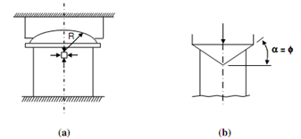
Most significant factor that has to be prohibited in compression test is the application of load. The load's axiality has to be ensured. The platen, generally the one in contact along with the moving cross-head is made self aligning along with a spherical head on the top of the plate that is directly in contact with the test piece or specimen. The centre of the spherical head coincides along with the centre of the specimen top surface via which should pass the axis of the machine. Great care requires to be exercised for aligning the test piece specimen axially along with machine following figure (a).
Due to friction among the loading plate and upper side of specimen the material immediately below the upper surface is subjected to close to hydrostatic stress and ignores failure. Via compressive stress in direction perpendicular to load axis reduces away from loading surface it does not damage before distance is in any case diameter of the specimen. For this purpose the specimen length of 3d is generally recommended. The top surface is also recommended to be friction free and smooth. In various specimens close cut circular concentric grooves and produced to hold lubricant, mostly in specimens of ductile materials. The problem of bulging is minimal in concrete and thus l/d = 2 are often employed for this material. Till now another method the ends are made conical hollow to obtain similar loading plate as represented in Figure (b). The angle of cone is equivalent to angle of friction among the materials of specimen and platen, and it is not readily identified. It is significant that compression force must be applied such as rate of straining is constant. Mainly materials needed to be tested in compression are visco-elastic in nature and do not attain equilibrium readily. Given strain rates are, hence, maintained.

Figure: (a) Self Aligning Platen; and (b) Conical Hollow End of Compression Specimen