Critical bending moment:
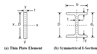
However, thin plate elements when subjected to transverse loads tend to buckle and, therefore, bend into a plane which is away from the plane of bending; this is because Iy is much small as compared to Ix (Figure a). This off-plane bending further aggravates the bending stresses and they cannot be calculated by Eq. From advanced analysis, it is called that for a narrow rectangular plate beam, subjected to pure bending (end couples only), the critical bending moment is given by Figure (a).
Mcr = π/L 
where G = Shear modulus (for steel, 0.8 × 10⁵ MPa),
K = St. Venant's torsional constant,
L = Effective length of plate, and
E = Modulus of elasticity (for steel, 2 × 10⁵ MPa).
For doubly symmetrical sections and I beams (Figure 2(b)) the right hand side is to be multiplied by a factor , where C is the warping torsional constant.
Thus,

Figure
However, in the application of the above formula it was found that the bending of such section was affected by the type of loading, the manner in which the beam restraint supported along its length L, a lateral restraint given, and the torsional restraints at the supports. In addition the above formula is not applicable for unsymmetrical section, e.g. channels etc.