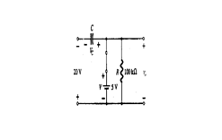
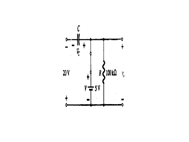
Q. Find out v0 for the network shown in the diagram.

SOLUTION:
Our analysis shall start at time t1 to t2 .our circuit shall behave as indicated in the diagram. By applying KVL to input loop
-20 + Vc - 5 = 0
Vc = 25V

The capacitor shall consequently charge up to 25V. In this the resistor shall not be shorted by the diode, however a Thevenin's correspondent circuit for that part of the network which includes the battery & resistor shall result in Rth = 0, with Eth = V = 5V.

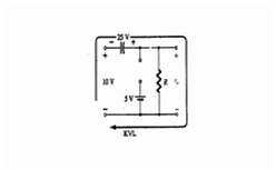
For the period t2 to t3 the circuit is indicated in the diagram.

By applying KVL across the outer loop
10 + 25 - Vo = 0
&
Vo = 35V
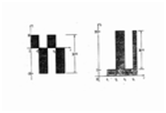
The time constant of the discharging network of diagram is find out by the product of RC and contain magnitude
T = RC = 0.01S
The output wave form shall obtain the shape like
