Points in the RC plane:
Capacitive reactance can be plotted along a half line just as can inductive reactance. Actually capacitive and inductive reactance, considered as one, form the whole line that is made of 2 half lines stuck together and pointing in opposite directions. The point where they join is zero reactance point. This was shown back in Figure.
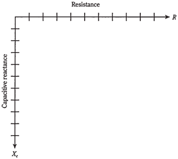
In the circuit having resistance and capacitive reactance, the characteristics are 2-dimensional, in a way that is analogous to situation with RL plane from the previous chapter. The resistance ray and capacitive reactance ray can be placed end to end at the right angles to make a quarter planes called as RC plane. Resistance is plotted horizontally, with the increasing values toward right. Capacitive reactance is plotted downwards, with the increasingly negative values as you move down.
The combinations of R and XC in the RC plane form the impedances. Each point on RC plane corresponds to one and only one impedance. On the other hand, each specific impedance coincides with one point on the plane.
Impedances which contain resistance and capacitance are written in the form R = jXC. Remember that XC is never positive, that is, it is always negative or zero. Because of this, engineers will often write R = jXC, dropping minus sign from XC and replacing the addition with subtraction in complex rendition of impedance.
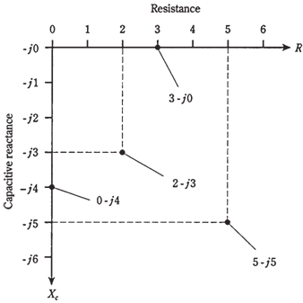
If resistance is pure, say R = 3 Ω, then complex impedance is 3- j0 and this corresponds to point (3,0) on RC plane. You might at this point suspect that 3 + j0 is same as 3- j0 , and that you really not even write the "j0" part at all. In theory, both of the notions are indeed correct. But writing "j0" part indicates that you are open to the

Figure-- The RC quarter-plane.
possibility that there may be reactance in circuit, and that you have working in 2 dimensions. It underscores the fact that impedance is a pure resistance. If you have the pure capacitive reactance, say XC = 4Ω, then complex impedance is 0- j4, and this is at point (0,4) on RC plane. Again, it is essential, for completeness, to write "0" and not just the -j4.
The points for 3- j0 and 0 - j4, and 2 others, are plotted on RC plane in the figure given below.
In practical circuits, all the capacitors have at least some leakage resistance. If the frequency goes down to zero, that is, if the source is direct current, a tiny current will flow as no insulator is perfect. Some capacitors have no leakage resistance, and come close to being perfect. However, none of them are mathematically flawless. All the resistors have a little capacitive reactance, because they occupy physical space. So there exists no such thing as a mathematically pure resistance. The points 3 - j0 and 0 j4 are idealized.
Resistance and capacitive reactance are both placed in the circuit deliberately. Then you get impedances like 2 -j3 and 5 - j5, both shown in the Figure given below.
Remember that values for XC are reactances, and not actual capacitances. They vary with frequency in an RC circuit. If you raise or lower frequency, the value of XC will change. A higher frequency causes XC to become smaller negatively. A lower frequency causes XC to become larger negatively (farther from zero, or lower down on RC plane). If frequency goes to zero, then capacitive reactance drops off bottom of the plane, out of sight. In that case you have 2 oppositely charged plates or sets of plates, and no action.

Figure-- Four points in RC plane.