Current leads voltage:
Capacitance stores the energy in the form of an electric field. When the current is driven through the capacitor, it takes a little time before plates can totally charge to the full potential difference of source voltage.
When an alternating current voltage source is placed across the capacitor, the voltage in capacitor lags the current in phase. Another way of saying this is that current leads the voltage. The phase difference may range from zero, to the small part of a cycle, to the quarter of a cycle (90 °).
Pure capacitance
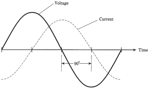
Imagine placing an alternating current voltage source across a capacitor. Assume that the frequency is high enough, and the capacitance large, so that the capacitive reactance, XC, is extremely small as compared with the resistance, R. Then current leads the voltage by a full 90 °.
At high frequencies, it does not take very much capacitance for this to happen. Small capacitors have less leakage resistance usually than the large ones. At the lower frequencies, the capacitance should be larger, although high quality, low loss capacitors are not too difficult to manufacture except at the audio frequencies and at 60-Hz utility frequency.
The situation shown in figure given below represents a pure capacitive reactance. The vector in RC plane points about straight down. The angle of it is 90 °from the R axis or zero line.

Figure-- In a pure capacitance, the current leads the voltage by 90 °.
Capacitance and resistance
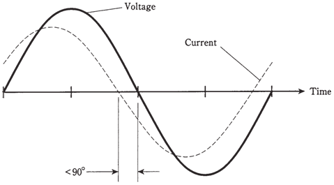
When resistance in resistance capacitance circuit is important compared with the capacitive reactance, the current leads voltage by something less than 90°. If R is small compared with XC, difference is almost the quarter of a cycle. As R gets larger, or as XC becomes smaller, phase difference gets less. A circuit containing resistance and capacitance is known as RC circuit.

Figure-- In a circuit with capacitance and resistance, current leads voltage by less than 90 °.
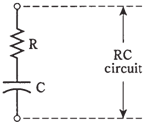
The value of R in the RC circuit may increase relative to XC as resistance is deliberately put into the circuit. Or, it might happen as the frequency becomes so low that XC rises to the value comparable with the leakage resistance of capacitor. In any case, the situation can be represented by the resistor, R, in series with the capacitor, C .

Figure-- Schematic representation of an RC circuit.
If you know the values of Xc and R, you can find angle of lead, called as RC phase angle, by plotting point R = jXC on RC plane, drawing vector from the origin 0 - j0 out to that point, and then measuring angle of the vector, clockwise from resistance axis. You can use the protractor to measure this angle. Or you can use trigonometry to calculate angle.
As with the RL circuits, you are required to know the ratio of XC to R to determine phase angle. For instance, if XC =4 Ω and R =7 Ω, you will get the same angle as with XC = 400 Ω and R =700 Ω, or with XC = 16Ω and R = 28Ω. The phase angle will be = same for any ratio of XC:R = -4:7.
Pure resistance
As resistance in the RC circuit gets large compared with the capacitive reactance, the angle of the lead becomes smaller. The same thing happens if value of XC gets small compared with value of R. When you call XC large, you mean very large negatively. When you say that XC is small, it is close to zero or small negatively.
When R is several times larger than XC, whatever may be their actual values, the vector in RC plane will be almost right along R axis. Then RC phase angle will be zero, which is, just a little bit negative. The voltage will come into phase with current. The plates of capacitor will not come anywhere near getting the fully charged with each cycle. The capacitor will be said to pass the alternating current with very little loss, as if it were shorted out. But it will still have extremely high XC for any alternating current signals at much lower frequencies which might exist across it at the same time.
Ultimately, if capacitive reactance gets small enough, the circuit will behave as a pure resistance, and the current will be in phase with voltage.