DC Biasing-BJT:
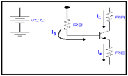
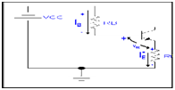
Emitter-Stabilized Bias Circuit

Base Emitter Loop

KVl Equation given for the loop is
VCC-IBRB-VBE-IERE=0
But IE=(β+1)IB
Thus,
VCC-IBRB-VBE-(β+1)IBRE=0
-IB(RB+(β+1)RE)+VCC-VBE=0
IB=(VCC-VBE)/(RB+(β+1)RE)
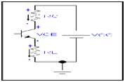
Collector-Emitter Loop

IERE+VCE+ICRC-VCC=0
But IE=Ic
VCE-Vcc+Ic(Rc+RE)=0
Vce=Vcc-Ic(Rc+RE)
Now VE is the voltage between the Emitter terminal and the ground, provided by
VE=IERE
Also Collector to ground voltage is
VCE=VC-VE
VC=VCE+VE
Also Vc=VCC-IcRC
Voltage at the base w.r.t ground is
VB=VCC-IBRB
VB=VBE+VE
Stabilization:
Because of addition of the emitter resistance the values of DC bias currents and voltages stays constant with any variation in the Temperature and transistor beta.